Hello everyone,
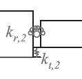
I am trying to figure out how to include the properties of an internal translational and/or rotational spring between two beams.
Modelling in 2D and beam elements I always get an error at the end (when submitting the job) of "THE NAME ASSEMBLY_Beam right-1_None HAS BEEN USED ON A PREVIOUS ORIENTATION DEFINITION. ORIENTATION NAMES MUST BE UNIQUE". This is hapenning even if I model the two beams separately (assigning a different orientation every time) as two parts and then assembling.
The problem is I do not know how to include the properties. Should I use a connector to define the properties? And if yes which one? Because I just use beam elements. Or is it only by including a spring from the Engineering Features, "connected to two dots" ? And if yes how? Because for beam elements there are no two nodes to choose, just the one common (connecting the two beams).
I attached a picture of the model I need to define.
Thank you in advance for your response


