Continue to Site

Eng-Tips is the largest engineering community on the Internet

Intelligent Work Forums for Engineering Professionals

  • Congratulations MintJulep on being selected by the Eng-Tips community for having the most helpful posts in the forums last week. Way to Go!

Interpretation of a true position geometric tolerance 1

Status
Not open for further replies.

ldffernandes

Mechanical
Oct 14, 2015
7
Hello,

I would like to ask for your help in interpreting the true position geometric tolerance of the attached drawing.
I believe it specifies that the axis of the pocket with diameter DIM A should be contained inside a cylinder with diameter 0.3 and whose axis:
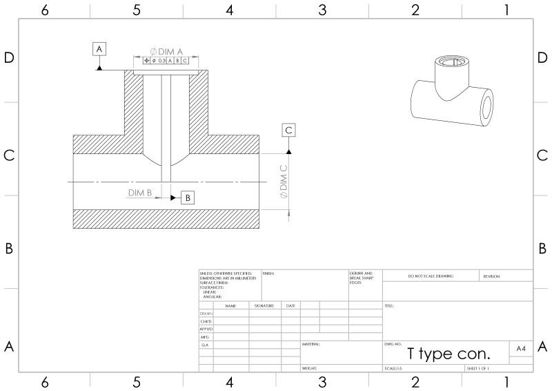
- is perpendicular to the face with datum A;​
- is coincident with the plane defined by datum B;​
but I don't understand what constraints datum C imposes. Can you help me figure it out?


t_tube_qz5zev.jpg
 
Replies continue below

Recommended for you

ldffernandes,

Datum feature C constrains the final remaining degree of freedom, which is translation in the direction perpendicular to the section view cutting plane.

This strikes me as a rather strange tolerance scheme.


pylfrm
 
ldffernandes,

I agree with pylfrm. I would use one of the diameters perpendicular to datum feature[ ]A to control location, and use either the slot, or your datum feature[ ]C to control rotation.

--
JHG
 
Assigning X to the right, Y up, and Z out of the page with AX, AY, and AZ as the angles of rotation about them then:

[pre]
X Y Z AX AY AZ are initially free motions.

Y AX AZ are controlled by A
X AY AZ are controlled by B
Y Z AX AZ are controlled by C[/pre]

Any previously controlled degrees of freedom are ignored in later datum references.
[pre]
X Y Z AX AY AZ are initially free motions.
subtracting:
Y AX AZ are controlled by A
leaves
X Z AY
then subtracting:
X AY AZ are controlled by B (ignore AZ because it is already used)
leaves
Z
then subtracting:
Y Z AX AZ are controlled by C (ignore Y, AX, and AZ, as they are already used.)
removes the last degree, Z
[/pre]

There is little reason to think the given set of datums is meaningful, especially without any suggestion as to the relations between the datum features and without the mating parts or their tolerancing. In fact, given the shallow depth of the feature chosen for B, it is suspect all around. Even a slight misalignment in cutting the groove could make determination of C very difficult.
 
pylfrm,

Thank you, that makes sense.


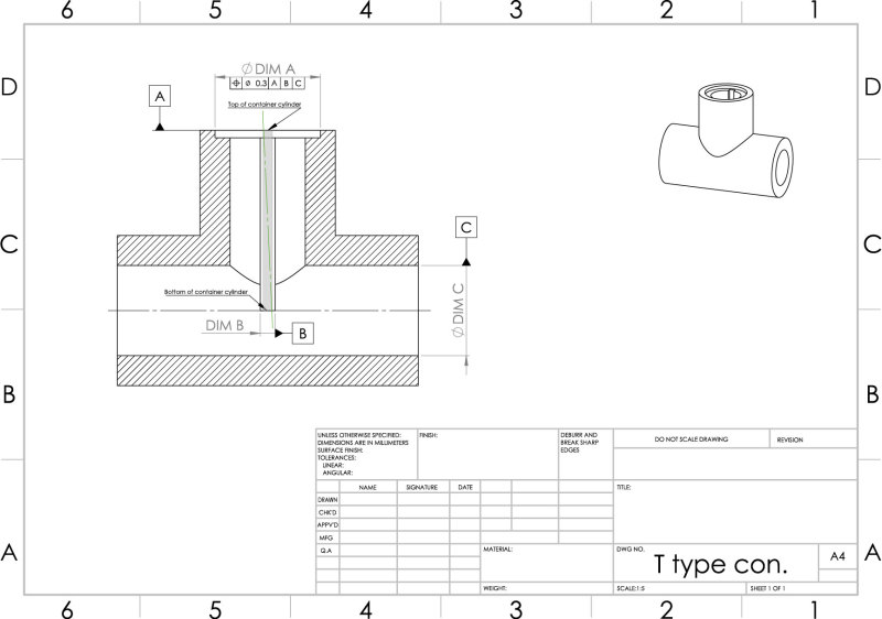
I have one final question: do datum feature A and datum feature C define the top and bottom, respectively, of the theoretical cylinder that contains the axis of the pocket? I.e.: is the attached drawing correct (where the green axis represents the axis of the pocket and the grey square represents the theoretical cylinder)?

t_tube_cqtig7.jpg
 
ldffernandes,
The length of the tolerance zone dia. 0.3 cylinder equals the depth of the short cylinder of dia. DIM A. It does not go any deeper, so your drawing is incorrect.
 
pmarc,

Thank you for your answer, that was what I was expecting. May I ask you if you can tell me which paragraph in ASME Y14.5 explains it?
 
Paragraph 1.4(n)


John-Paul Belanger
Certified Sr. GD&T Professional
Geometric Learning Systems
 
As J-P said, it is 1.4(n) in Y14.5-2009.

If you are using Y14.5M-1994, it is 1.4(m).

If you are using ISO or ISO-related standard (your drawing looks a little bit ISO-ish), then it is para. 4.6 in ISO 1101:2012.
 
Didn't mean to jump in on things, pmarc. I wasn't sure if you had gone to bed yet, and I didn't want the poor guy to wait until tomorrow for an answer. [bigsmile]

John-Paul Belanger
Certified Sr. GD&T Professional
Geometric Learning Systems
 
No need to explain yourself, J-P. This discussion is not only between me and OP. In fact I too jumped in on it today. I hope pylfrm and 3DDave will forgive me for that.
 
Belanger and pmarc,

Thank you both for your time and great answers. Your answers sparked a few further questions, if you don't mind:

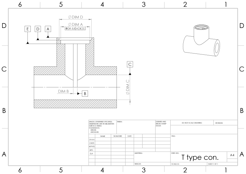
- In the attached drawing what is the length of the theoretical cylinder that contains the axis of the pocket with diameter DIM A: is it the length of the perpendicular distance from datum feature D to datum feature E?​
- If so, what if (and even though it may not make sense from a production point of view, but bear with me please) the pocket with diameter DIM A was machined before the pocket with diameter DIM D; would it make the length of the theoretical cylinder that contains the axis of the pocket with diameter DIM A any different from the previous situation?​


t_tube_2_ts3n76.jpg
 
1st question -- Yes, it is the depth of that full DIM A diameter, as produced. (If there is a bottom radius on that diameter, then the position tolerance stops short of that; it's only for the straight-walled diameter.)

2nd question -- It doesn't matter how it's produced. The position tolerance only applies for the depth of the finished part's DIM A.

John-Paul Belanger
Certified Sr. GD&T Professional
Geometric Learning Systems
 
Gentlemen,

Thank you very much for your time and promptly replies.
 
Status
Not open for further replies.

Part and Inventory Search

Sponsor