Continue to Site

Eng-Tips is the largest engineering community on the Internet

Intelligent Work Forums for Engineering Professionals

  • Congratulations SDETERS on being selected by the Eng-Tips community for having the most helpful posts in the forums last week. Way to Go!

Interrupted profile tolerancing

Status
Not open for further replies.

Wuzhee

Automotive
Jul 12, 2022
292
Hi.

I have a part, attached below. This is a press die holder. A loose fitting die will lay inside the funky shaped area (highlighted).
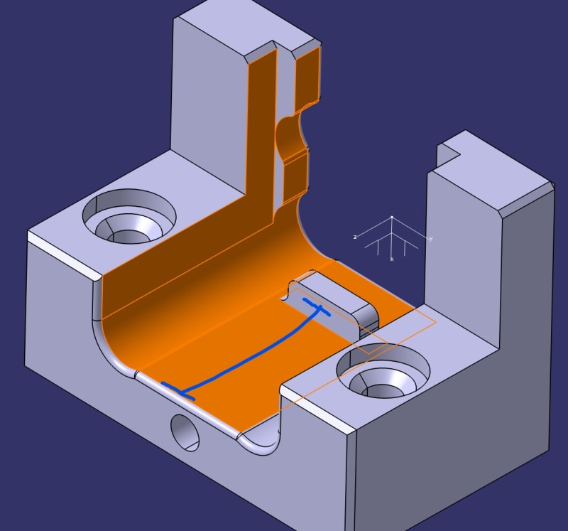
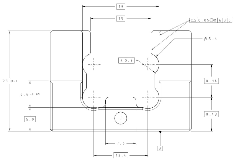
PROFILE_SEGMENTS_jvv3tc.jpg


Drawing view:
ortho_ectqw4.jpg


Now the problem:
First I want to control the die area going from the 15 mm opening to the bottom thickness of 5.9 mm.
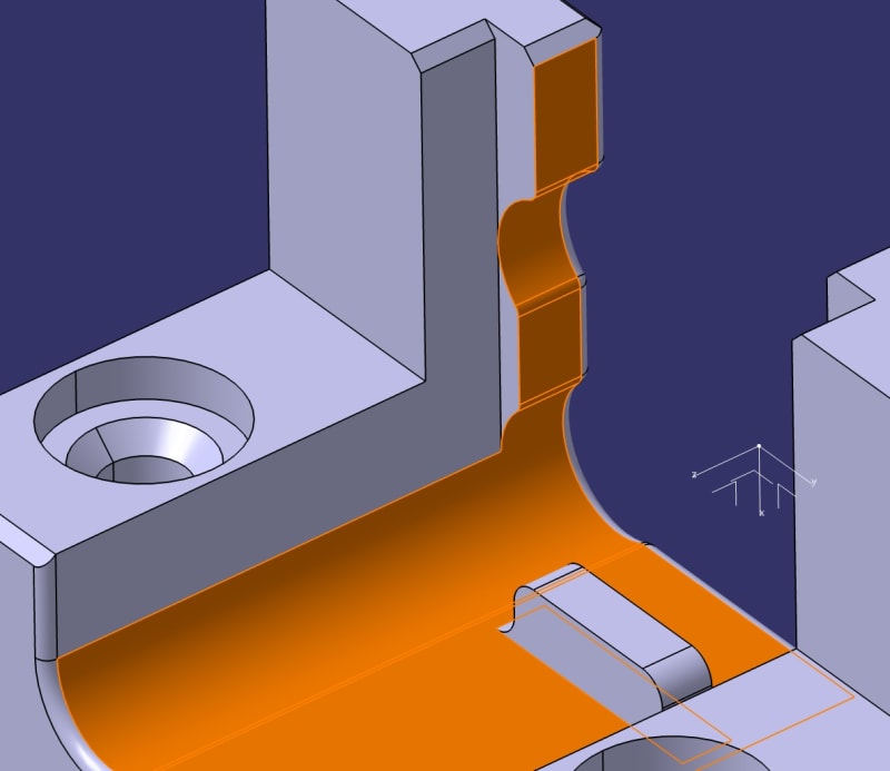
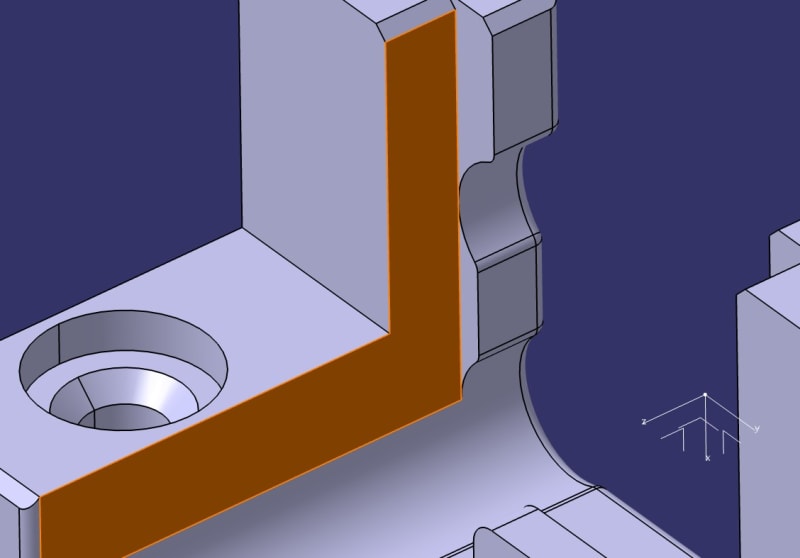
Second I want to control the 19 mm wide opening up to the ledge on the back.

How is this possible? Is my current profile sufficient enough? It will affect the surface behind the middle ledge am I right?

EDIT: I left out some dimensions by mistake but I think my point went through.
 
Replies continue below

Recommended for you

Firstly, currently the profile tolerance only applies to the surfaces the leaders point directly to.
If you want the tolerance to apply along contours that include multiple features, you have to designate points on the drawing view by letters and use the "from-to" "between" symbol for each separate profile feature control frame (If I understand correctly, you want separate controls even though it's not currently shown).
Secondly, if the bottom surface is continuous around the ledge, any surface profile tolerance that includes it will apply to all its portions as a whole.
If you really need to separate the surface to apply different tolerance values to it (do you?) you can try showing the "limited length or area indication" (per the Y14.5 standard) on a top view and clarify by a notation under the profile FCF in the front view which portion of the bottom surface is controlled. Notations could state something like "INCLUDES AREA A" and "EXCLUDING AREA A".
 
I assume because of tangent continuity the profile tolerance goes all the way to the first sharp edge, in my case the chamfer.
I want to control simultaneously this:
this_abupcq.jpg

And that:
that_qpurd8.jpg

Because of tangency between the width and diameter I want to control them both at the same time.

I don't care about the ledge in the middle, that's directly toleranced and not that important. If the profile applies to it, then let it be, few dimensions less, not a big deal.
I'm having problems with the tangent zones. And the steps between 19 and 15 (and 17 below)
 
Wuzhee,

The current profile tolerance would only apply to the two planar surfaces that the leader arrows are directly pointing to. The usual Y14.5 method for indicating profile zone coverage is to use the between symbol and annotation points (e.g. P <--> Q ). See figures 11-8 and 11-9 in Y14.5-2018. However, this method is very limited - it only really works on surfaces with constant cross section. Your surface has different cross sectional shape at different "depths", and has an interruption where the boss is. It's very difficult to indicate areas like this using 2D views - the best way to make it clear would be to include an iso view with the intended area shaded.

Evan Janeshewski

Axymetrix Quality Engineering Inc.
 
axym said:
It's very difficult to indicate areas like this using 2D views - the best way to make it clear would be to include an iso view with the intended area shaded.

Evan, Burunduk, or anyone who knows the answer,

Do you think it is ALLOWED by the standard to dimension a feature in an ISO view? I always been under the impression (which could be very well wrong assumption) that you are not allowed (actually it is forbiden) to indicate a feature definition into the ISO view on a 2D drawing.
Therefore, if a 2D drawing is chosen as a method to communicate the design intent THEN all the feature's definition shall be shown in the applicable 2D views (front, left, right, section views, details), but NOT into the 3D ISO view. ISO view it is there / it is shown for easy to understand the part/drawing, but no dimesnions, tolerances should be part of the definition on the ISO view

Am I wrong?

Please kindly advise.

 
Whuzhee said:
I assume because of tangent continuity the profile tolerance goes all the way to the first sharp edge, in my case the chamfer.
That assumption is wrong.

Whuzhee said:
Because of tangency between the width and diameter I want to control them both at the same time.
You need 2 profile feature control frames referencing A, B, C. One, as Evan pointed out, with a "from-to" "between" indication to control the 15 mm width, all the radii and the bottom surface. Another one with two leaders, one for each planar surface of the 19 mm width.
If you're working per ASME, they all will be in a Simultaneous Requirement because of the identical datum references in the same order. Hence, you will "control them both at the same time".
 
Burunduk said:
If you're working per ASME
Yes, 2018 edition.

Burunduk said:
Quote (Whuzhee)
I assume because of tangent continuity the profile tolerance goes all the way to the first sharp edge, in my case the chamfer.
That assumption is wrong.
In that case, even if a feature has radii between the surfaces the tolerance applies only to that surface where the leader is pointing to. So this is why the standard says "Where the extent of the application of the profile tolerance is unclear, the “between” symbol should be used." (11.2.1.1) and "When a profile tolerance applies all around the true profile of the designated features of the part (in the view in which it is specified), the “all around” symbol is placed on the leader from the feature control frame." (11.3.1.3)
Figure 11-24 to 11-29 backs that up by always indicating the all-around specification.

Thanks, all clear now. I was using it wrong then and encourage my colleagues to follow my methods [hammer][spineyes]
 
Status
Not open for further replies.

Part and Inventory Search

Sponsor