Continue to Site

Eng-Tips is the largest engineering community on the Internet

Intelligent Work Forums for Engineering Professionals

  • Congratulations GregLocock on being selected by the Eng-Tips community for having the most helpful posts in the forums last week. Way to Go!

Introduction & Pump Foundation 1

Status
Not open for further replies.

RattlinBog

Structural
May 27, 2022
177
Good Evening,

I'm a long-time reader and first time poster. This is a great forum. I'm a structural EIT with a little over four years of experience. I started in consulting (mostly heavy industry work) but switched to the client side working at a mine less than a year ago. I'm the only structural on site, but there are a couple structural PEs at other mine sites under the same parent company. I'll be taking the PE exam in August. I'm also halfway through an M.S. Civil Engineering degree. I'm very slowly climbing out of the valley of despair of the Dunning-Kruger curve.

I thought it wouldn't be appropriate for my first post to be massive, but I could use some technical assistance. I'm designing a 'partial' foundation for a 250 HP pump. I say partial because we are reusing an existing 2'-8" deep foundation from an old pump, though I still need to analyze it for new loads. This is my first design for a foundation supporting dynamic equipment. (I am aware of ACI 351.3-18 but do not own a copy.) Below is a list of items I have or am planning to consider in my analysis and design. Would someone let me know if I should modify my list? It has occurred to me to contact the pump manufacturer about some of this, but I haven't done that yet.

Checklist:
- calculate forces on foundation and anchors from pump torque and thrust (I am factoring these forces by 3 to account for any harsh startups or other dynamics)
- compare concrete mass to equipment mass (a senior engineer I used to work with told me to size equipment foundations to be 2-3 times the mass of the equipment to mitigate vibration)
- design adhesive anchors per ACI 318 Ch. 17 (I have a Mathcad sheet but also plan to use Hilti Profis) (I'm assuming F1554 Gr. 36 threaded rods with snug-tight nuts and washers.)
- design sole plate beneath pump base for bending (assuming it loses contact with grout)
- determine installation details such as providing leveling screws or jam nuts to level sole plate; and providing a grout hole in sole plate
- spec grout (need to research if cement or epoxy grout is better suited here)
- check existing concrete foundation for shear, bearing, and possibly bending

What am I missing? As I get farther along in the design, I can provide more details and values. Thank you!

 
Replies continue below

Recommended for you

Get a copy of API 610. It has a lot of good practices for pump foundation, grout, etc... and has a very detailed checklist that you are looking for.

I don't think you need a sole plate. But check with your Rotating Equipment Engineer if your plant normally use sole plate for pump. We usually don't.

We usually use epoxy grout and also fill the pump base/skid with epoxy grout. This can be expensive and better check with your rotating equipment engineer.
 
Hi RattlinBog

We used to mount the pump and motors on a frame, the frame usually was C section and with the flanges pointing inwards on all sides we would pour grout into the frame and let it fill to the entire depth of the C section, one important thing is to make sure you have lifting points on the frame that are accessible and you might be able to lift the frame, pump and motor all in one but that would depend on the design.
Your list looks pretty good to me but this might help it’s an installation manual for a company I did some work for
Yes you should contact the pump manufacturer because they will probably have specific requirements on how the pump should be installed.

“Do not worry about your problems with mathematics, I assure you mine are far greater.” Albert Einstein
 
RattlinBog said:
What am I missing?

Soil bearing pressure. It probably won't govern, but should be checked. The weight of the pump, the overturning due to vibration, and the lateral force due to vibration should all be considered.

DaveAtkins
 
RattlinBog said:
design adhesive anchors per ACI 318 Ch. 17 (I have a Mathcad sheet but also plan to use Hilti Profis) (I'm assuming F1554 Gr. 36 threaded rods with snug-tight nuts and washers.)

I wouldn't consider using adhesive anchors for a pump this big. Whenever vibrating equipment is involved, I recommend using cast-in-place sleeve anchors, or a sole plate with welded studs to match the bolt pattern of the mounting flange.

The problem without using sleeves is that the bond between the concrete and the anchor is critical to ensuring that the anchor is adequately pre-tensioned. Once things start vibrating, that bond becomes broken, and it compromises the pretension. This can lead to long term maintenance issues (e.g. failed seals, excessive vibrations, worn out bearings, and etc).

See PDF page 3 for a detail.

Here's a good article from Meca.

Here's a remark from HILTI.

Here's a quote from ACI 351.3R-04
"A long-established rule-of-thumb for machinery on blocktype foundations is to make the weight of the foundation block at least three times the weight of a rotating machine and at least five times the weight of a reciprocating machine."
 
CrabbyT, concrete is existing. He will need grout pocket to do what you are suggesting.
 
Thank you for the replies.

AskTooMuch, I will look at getting a copy. I called our pump vendor about the sole plate and grout recommendations--he's going to look through the Warman manual and get back to me.

desertfox, I briefly skimmed your reference. It looks like it's mostly mechanical instruction, but I'll look more closely later. I saw one general paragraph on foundations.

DaveAtkins, good point; I will add it to the list.

CrabbyT, echoing AskTooMuch, I believe that may be more challenging since my foundation is existing. There's the option of demo and pouring a new foundation, but I would prefer to avoid that. I did read through your references and will save them, though.

If it makes any difference, this 250 HP Warman 10/8 F-AH slurry pump is going to operate at a duty point of 2500 gpm and 39 ft TDH and BHP = 82 at 402 rpm. However, I was also provided a max duty point of 3900 gpm at 80 ft TDH and BHP = 254 at 580 rpm. I've decided to calculate torque from the max duty point. I'm getting torque, T=(5252*HP)/RPM = 2.3 k-ft. If I take the advice of the senior engineer I used to work with, I multiply that value by 3 for dynamic effects to get 6.9 k-ft and then multiply by 1.6 for LRFD combo 2 to get 11 k-ft of torque. Anchors are spaced 30 inches, so the two anchors on one side receive 2.2k tension each. I'm ignoring dead load for any torque resistance. As a prelim check in Hilti Profis, I'm seeing utilizations of 35% concrete breakout and 22% bond. I'm checking Hilti's HIT-HY 200 V3 with HAS-E rod. The pump anchor hole is 1 3/8", so I believe I need to default to 1 1/4" anchor.

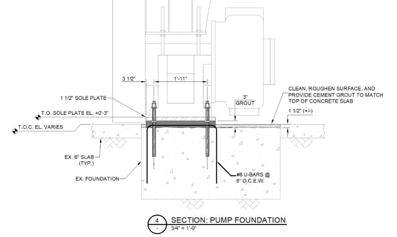
For a fun twist, one challenge I'm discovering is that the old pump foundation has had the top +/- 3" (or more) jack hammered away. Consequently, the #6 rebar top mat was demo'd. Not a fan. The old foundation is L-shaped, roughly 11'x11', and previously supported a pump and gyrol. Our new pump will not have a gyrol, so it will sit on roughly a 3'x3' portion. My edge distances are a bit tight, too, at 5" to anchor center at the worst. I'm considering providing a #3 tie around the anchors for shear and adding 3" grout below a sole plate. Does any of this sound concerning? I don't love that the old slab is no longer intact.

I'm attaching a preliminary section. Thanks in advance.
 
 https://files.engineering.com/getfile.aspx?folder=cf679745-c4c6-40b9-8334-d87496b06542&file=pump_fdn.jpg
I gave the demo'd concrete a little more thought. I'm going to have one of our maintenance guys take a long bit and drill a sample hole in the foundation to determine its remaining depth. My gut is starting to tell me that more than 3" was demo'd. I would hate to only have half of the foundation remaining. If it's thin, I'll have to cut out a chunk and repour with CIP anchors.
 
I would also be very suspect of using ACI design methods to anchor to a slab that does not have a top mat of reinforcing. Others will have a better understanding than me but ACI design relies on the reinforcement for concrete integrity. You can take a look at the commentary in ACI 318.
 
GC_Hopi, agreed! I'm finding out some of these things in real time as I dig deeper. The more I dig, the more crap I find!
 
You need to do at least a simple frequency check that the pump-foundation is not in resonance frequency.

Fn = 2253 sqrt( K/Pg)

K = subgrade modulus
Pg = gross soil bearing pressure
 
JoelTXCive--thank you very much! That will come in handy.

Here's an update. I was able to have somebody drill a hole in a discreet portion of the foundation and confirm that we still have at least 22" thickness remaining. However, there's still the issue of the top rebar mat (#6 u-bars at 9" O.C.) having been demolished (the vertical parts remain embedded).

Before I spend too much time analyzing this existing foundation which may or may not be adequate, would anyone care to share their opinion on the options of: 1) working with what I have or 2) demo and start with a new foundation? Please bear in mind that I'm still hovering in the conceptual phase and have not run through many design calculations yet. I would rather sharpen my axe before I fell the tree.

I have one idea and a couple concerns with option 1. My idea is to replace the top rebar mat by doweling and epoxying in U-bars each way on a grid and casting in 3" of grout. I could also install hairpins around each anchor to help with shear, if needed. My concern with the replacement U-bar grid idea is whether I can even quantity or count on it to contribute to strength or mitigate cracks. My second concern is about my edge distance of 5". In ACI 318-14 section 17.7.3, minimum edge distances of 6da for adhesive anchors and 8da for torque-controlled anchors are specified. For da=1.25", 6da=7.5" and 8da=10", so no good.

I'm starting to lean toward option 2 of demo and replace. Then I can provide adequate edge distance, appropriate reinforcement, and cast-in anchors. However, I would love to hear any takes on option 1 or 2 or if anyone has faced a similar situation.

Prelim section showing doweled & epoxied u-bars:
u-bar_idea_nddo8q.jpg
 
Your 1st option is cheaper if it works. I personally don't see why it won't work though I have not run any calculation. Demo and putting new foundation will be much more expensive. I work inside a plant and have done several of these new pump replacement and using same foundation. So far no complaints lol.
I noticed, based on your answer, no one from the plant rotating equipment engineer group helping you (not equipment vendor).

I'd be very worried if we are talking about big compressor but small pump not so much.
 
AskTooMuch, thanks for your insight; I'll keep it in mind over the next couple days as I make a decision.

Not to beat up on our plant engineering group, but we're fairly lean. We do not have a rotating equipment engineer. Engineering used to be a bigger department, but there was a big layoff a few years ago when steel prices took a dump. Some retired, too. A lot of the engineers we do have end up doing project management more than anything. There are more engineers at sister plants, and I'm slowly getting to know them. I'm currently on a bit of an island doing technical work at my site, haha. I reach out to my contacts from consulting as needed (or hire them), but I thought Eng-Tips would be a nice resource to fill some gaps in knowledge. I never hope to be spoon-fed here! I enjoy the challenge of digging and learning; though it helps to have breadcrumbs to follow. Sometimes my battle is not knowing what I don't know.
 
AskTooMuch, I should have called myself TalkTooMuch because I can get wordy. :)

Just spit-balling here, I may run through some calcs from ACI 318-14 chapter 14 for plain concrete design and see if I can get anything to work. I haven't gone through that chapter before, but maybe it's worth sharpening my pencil a little on option 1. Perhaps if I can get a plain concrete foundation to work, I could still dowel in u-bars and feel better. I definitely want some steel at the top for crack control as a bare minimum. I'm going to look through ACI 351 to see if it has any comments on plain concrete, too.
 
Some consulting engineering firms have good design guide for pumps foundation. For small pumps with block foundation, it's U rebar of #5 on all faces of the block usually.
Big pump/compressor will require rebars in layers interally. Like lots of lots rebars per ACI 351 good practice recommendation and very deep pretensioned anchor bolts.
 
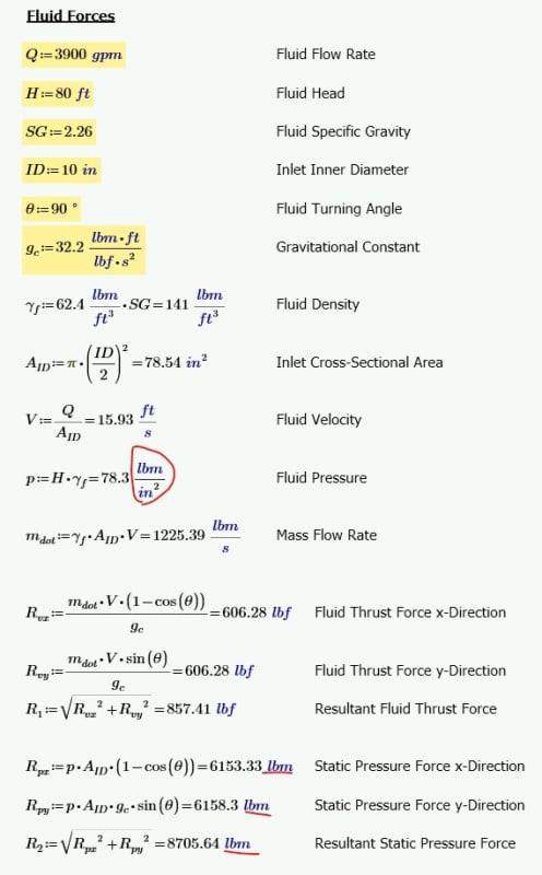
I've calculated fluid thrust forces using the max duty point and assuming a 90 deg change in direction from suction to discharge. I will use these values for shear on my anchors. I don't expect anyone to look over my work, but if anyone sees a glaring error, I'd appreciate a heads up.

fluids_forces_bbbhzl.jpg
 
lbf/ft^3 doesn't sound like the right unit for density in the terminology I'm used to (I'm used to density in units of lbm/ft^3).
Although I think you compensated for that error (*) by adding g (g = 1 lbf/lbm) where it doesn't belong (*) in the equations for p and R... so I think all those "errors" (*) end up cancelling out (in which case it doesn't matter... as long as no-one else is going to look at it).

(*) maybe these aren't errors and just a different terminology/convention than I'm used to. If so, I apologize.

=====================================
(2B)+(2B)' ?
 
electricpete, I think you're right on, but I also think we're getting to the same destination from different paths. I believe you are more technically correct, but I'm finding that using density in lbm/ft^3 messes with my pressure, which should be in lbf/in^2. (Unless I'm missing a conversion somewhere.) I'm just used to using lbf for everything in structures and soils.

Below are the same calcs using lbm vs lbf. I'm getting the same values as above, except now my velocity force is in lbf and my pressure force is in lbm. I'm referencing the Civil Engineering Reference Manual for the PE Exam, 14th Ed. by Lindeburg: Chapter 17 Fluid Dynamics, Section 38 Impulse-Momentum Principle. To calculate the "constant force required to accelerate or retard a fluid stream", for US customary units, the equation is F = (mass flow rate * change in velocity) / gravitational constant

where,

mass flow rate [=] lbm/sec
velocity [=] ft/sec
gravitational constant [=] (lbm*ft)/(lbf*sec^2)

I also used Engineering Toolbox to double check my numbers: Link

fluid_forces_dfudsy.jpg
 
Status
Not open for further replies.

Part and Inventory Search

Sponsor