Eng-Tips is the largest engineering community on the Internet

Intelligent Work Forums for Engineering Professionals

Inventor Tolerances for an inspection drawing

Status
Not open for further replies.

misterblode

Mechanical
Feb 22, 2013
9
0
0
US
Hi all,

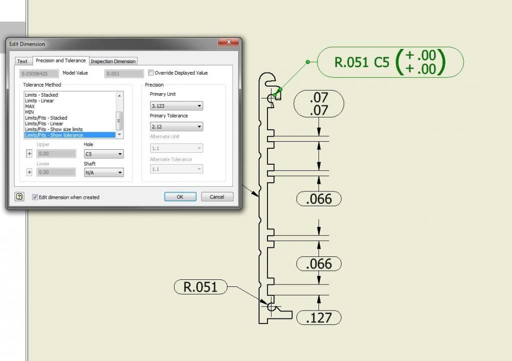
I feel like this should be fairly straight forward but I seem to be missing something. I am trying to create an inspection drawing showing some key dimensions that need to be checked and also show their tolerance. The difficult part is that I want to be able to individually set the tolerances for each dimension (this wont always be the case but I am working on an exception).

I was able to show the tolerance next to the dimension like I want, I just cant change the tolerance, it is grayed out. Does anyone know how I can individually edit the tolerance? I know I can globally change the tolerance with the style editor, but I would like to be able to individually change it.

Thanks!
 
Replies continue below

Recommended for you

There are two ways to do this.
The best might be to start by adding the tolerances to the dimensions in the part.
See Tools>Document Settings>Tolerances for setting up standard tolerances.
For the individual tolerances you can edit each dimension.
I will try to post an example later today.

Can you post a screen shot - not sure why you would be seeing editing grayed out.
 
Just something for you to look at.
I've been talking with these guys on and off for a few years.. They were supposed to have a version that tied directly to Inventor but I don't think it has been completed yet.
BUT it works pretty well with PDF files and can save you TONS of time if you have to create many inspection drawings.

However in Inventor (idw) you simply have to edit a dimension then go to the precision/tolerance tab and modify the tolerance there.

Can you define your steps exactly where you cannot edit a tolerance as it is "grayed out"?

It might be best to apply tolerances in the model and then pull the part tolerances in the drawing also.

But in general you have to make sure you select a tolerance type "default" will be grayed out but select deviation,etc.. and it will become active

There are numerous ways to accomplish it.
 
Perhaps I should also add a little detail of other information I am trying to use...and this might not work.

I'd like to use the 'C5' as a reference to that hole which will then appear in the inspection report, I do not want to use it as the 'hole size' Is this possible? Or is there a better way to do this?

This could be a reason the tolerance is grayed out.

toleranceinventor_zps566a0653.jpg
 
That is what I figured, just wondering if some how I could hack it to show the C5, or any letter and number, to then reference in an inspection report. I liked how easy it was to add the 'C5' to the drawing, next to tolerances. I guess I'll try something else.


This just lets you override the dimension, not the tolerance. So for this instance it would let me manually change the .051 radius to say .75- with out effecting the model.
 
Status
Not open for further replies.
Back
Top