Eng-Tips is the largest engineering community on the Internet

Intelligent Work Forums for Engineering Professionals

Inverter NP-Voltage deviation fault ABB ACS 1000 4

Status
Not open for further replies.

EL AABD Jamal

Electrical
Feb 22, 2017
23
0
0
MA
Dear All,

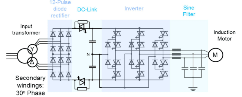
What could be the cause of the Neutral point unbalance fault in the inverter while the motor is running at low speed?

For information this is the sequence of events

183.58.3 "NP Voltage "
183.72.1 "AMC: Fault Class 2 "
6.21.7 "INU Tripped "
6.21.19 "INU StopCmd "
9.9.12 "Unbalance NP "
183.72.11 "INT: MCB Trip Req "
6.21.11 "MCB TripCmd "
9.9.0 "TrippLoop "
183.72.0 "AMC: Fault Class 1 "

Thank you in advance
 
Replies continue below

Recommended for you

Is the source to the VFD anything other than a solidly grounded wye?

I’ll see your silver lining and raise you two black clouds. - Protection Operations
 
the source to the VFD is a double secondary Transformer D/D/Y not grounded ( the rectifier is 12 Pulse rectifier)

abb_acs100_inkcsp.png
 
Do you reffer to neutral point (marked N in above schematic) inside of inverter?
This is a 3-level inverter and balance of neutral point is an issue... that depend of modulation index, power factor, modulation strategy.
Check settings about modulation / switching frequency and check power factor also.
Low motor speed is with low torque also? In this case power factor is very low.
 
Dear iop95, thank you for your response yes it's the point N marked in the schematic, and the fault occur at low speed which correspond to low torque (fan application), i didn't see the relation between the Vn balance and the speed, also in the troubleshooting manuel they suggest to check the motor Data and the Motor Model
 
Are you working on a new installation or has the drive already operated for some time ?

ABB has been promoting such kind of drives using reverse conducting IGCTs more than 10 years ago, but I'm not aware that such drives play a significant role on the market nowadays.

Potential reasons for such an unbalance can be manifold, just some examples here:

- offset of output current sensors
- leakage currents
- unequal propagation delay of drivers
- variation of swicthing delay of the power devices
- improper deadtime compensation

When designing such a drive such effects have to be considered and some balancing means habe to be implemented, either passive (resistors) or active (adaption of the modulation scheme. Motor data rarely have an impact
 
the drive has been operating for almost 10 years with no problems, an upgrade of it has been done recently which consist of software and hardware components,the problem is just occuring at low speed !!!
 
Is your unit watercooled ? According to a presentation of ABB the upgrade on the watercooled units also inlcudes the driver PCBs:


In general it is a good idea to do such an upgrade on large equipment after some years in the field (for the user as well as for the supplier), but this kind of service should provide the benefits which are used for marketing it.

I would be more pushy towards the supplier in your case. The problem is that for such case you are in a weaker position compared to a new installation where you can hold back significant amount of the total payment in case the equipment doesn't perform as specified.
 
NPC (Neutral Point Clamped) MV drives are supposed to be good at mitigating the CM noise that causes a neutral point shift, so if you are getting that specific alarm, I would suspect something is awry with your firing circuit and/or, as IOP95 said, a low power factor in the load (to which the output model is not properly tuned). Have you talked to ABB about this? My biggest concern here would be the beginnings of component failure in one (or more) of the firing boards, which could quickly cascade into a much more catastrophic and expensive power IGBT failure. You say that you recently had this drive "upgraded" with new hardware and software? I'm wondering if the new technician did not perform the necessary parameter adjustments needed for low speed operations (not that I know what they might be...). It's not commonplace to operate centrifugal fans at low speed because the fan generally will not perform at low speeds anyway, so he may have made assumptions and ignored this issue.


" We are all here on earth to help others; what on earth the others are here for I don't know." -- W. H. Auden
 
the response of ABB comissioning engineer is: "it was noticed that the drive tripped 3 times on NP voltage on very low speeds , this indicates that the motor model is not accurate 100% and this was clear while commissioning since the motor is very old and we don’t have the equivalent circuit we counted only on the name plate .

Evidently , if you really need to run on such low speeds, it was found that in some cases it is helpful to enable the new NP control functionality, to get rid of nuisance NP voltage faults.

134.09 NP CURR FILT (T2) -> 0.1
134.36 NP LIMITER -> ENABLE
134.43 NP ISIGN TIME LEV -> 25us (T1)"

now they made it clear that the model is not accurate, i'm afraid that it could do some damage to the MOtor that is an expensive one!! what do you think ?
 
As the NP control refers to the NP of the inverter, it is unlikely that there is a risk for the motor. Severe unbalance her would harm the inverter.

From my point of view a good inverter control should not rely on on a detailed motor model going beyond nameplate data. My view on this is clear:

If the drive ran proper for 10 years prior to the upgrade, it should do so also afterwards. If not I'd expect the supplier to fix it when installing the upgrade.
 
NP unbalance may afect DC bus capacitors and may lead to catastrophic failure in switching devices.
This upgrade seem to have problems at low speed ... and most probable have new digital control cards and seem have forgot or ignored zero sequence in NPC inverters that become a problem at low speed (low output frequency).
"Motor model" issue would have to affect motor control torque... not NP balance.
 
They relied only on the motor nameplate for the motor model? aBB drives are capable of doing an autotune (what they refer to as “ID Run”) to attain the necessary motor modeling. Did they not do that?

Was this an actual aBB technician, or a 3rd party company contracted to ABB (as they do in some areas)?

" We are all here on earth to help others; what on earth the others are here for I don't know." -- W. H. Auden
 
it was done by an ABB technician, according to him The autotune failed cause the motor is old (10 years of running)!! this is why he only relied on motor nameplate
 
Induction motor model is pretty same for more than 100years... not 10.
I think autotune failed because an issue (software) in new controll cards... but motor age may be a "good guilty".
 
I agree. I have never seen the age of a motor affecting the autotune procedure unless the motor insulation was deteriorated to the point of near failure. VFDs are really good at finding motor problems, so that might have been a missed red flag.


" We are all here on earth to help others; what on earth the others are here for I don't know." -- W. H. Auden
 
Why autotune option is there.ofcpurse it is to tune motor parameters that is motor inductance and resistance.asking to replace costly motor just 20 year old is surprise.

It seems software issue
 
Status
Not open for further replies.
Back
Top