Continue to Site

Eng-Tips is the largest engineering community on the Internet

Intelligent Work Forums for Engineering Professionals

  • Congratulations SSS148 on being selected by the Eng-Tips community for having the most helpful posts in the forums last week. Way to Go!

IRC Portal Frame Modification 4

Status
Not open for further replies.

XR250

Structural
Jan 30, 2013
5,945
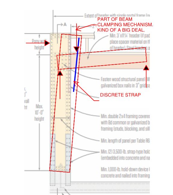
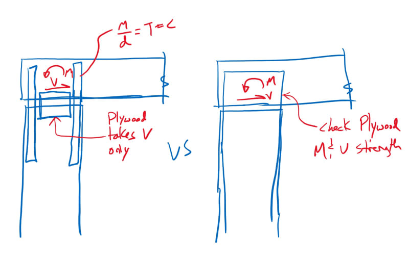
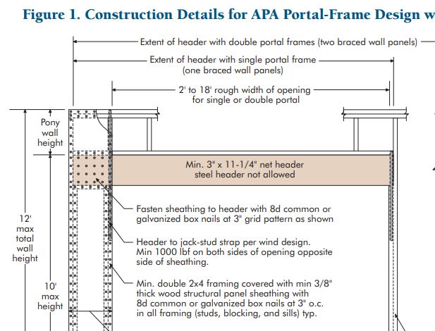
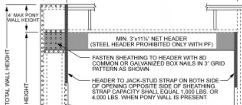
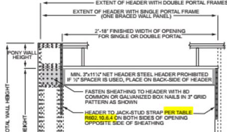
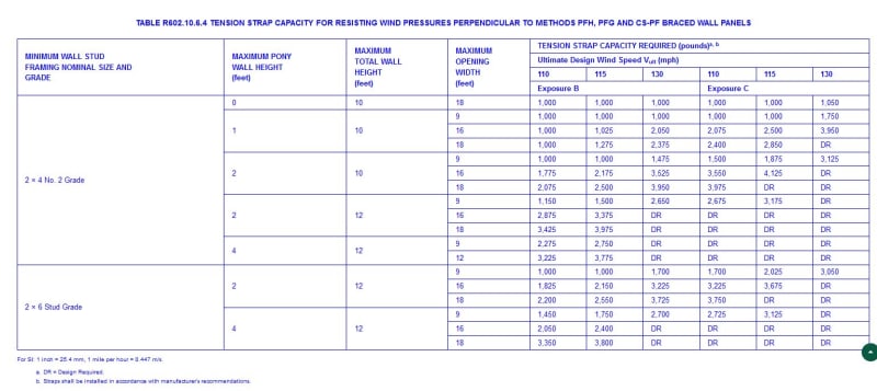
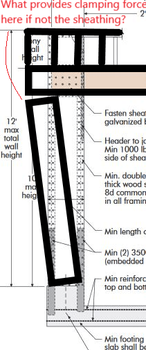
For Portal Frames with pony walls on top, the code requires a 4,000 lb. strap on the interior face of the wall. The contractor would rather sheath the inside face of the wall with OSB - identical to the exterior. Would that serve the same function as the strapping? Seems like it would.
Thanks
 
Replies continue below

Recommended for you

As long as they match the nailing pattern and panel arrangement it would probably be OK. Only concern would be with all those nails. If it's a 2x4 wall, the nails will be crossing each other from opposite sides and potentially turning the studs to splinters. Maybe have them mock up a panel and see what it does.
 
Thanks Pham. It is a 2x6 wall.
 
I vote no:

1) The interior sheathing will resist shear, just as the exterior sheathing does. That means that your nails will experience a combined demand from panel shear and the demand associated with direct tension that was originally the strap's job. There is something of a precedent for this in that sheathing fastening can be taken to resist shear and tension in combination when resisting uplift.

2) The sheathing panel itself has to be designed for direct tension stress. How wide of a chunk of sheathing can be assumed to participate in that given that it will be a concentrated edge load? I don't know the answer to that.

3) My understanding is that these setups have been corroborated by testing. Does your modification, to a critical part of the system, invalidate that? Again, I don't know.

In summary, I feel that the strap setup is great in that it creates a discrete tension resisting mechanism that would be predictable and separate from the shear panel function. I'd not want to give that up given that these particular straps create the beam clamping connection that really make this moment frame a moment frame from the perspective of both strength and stiffness. If it's me, I'm asking for the straps and looking to be cost friendly on some other, less mission critical element.

C01_wdtewn.jpg
 
Good points KootK. Perhaps I was a bit too quick to agree, though I'm not sure it would make a big difference in the end. Based on the way I read the footnotes in APA's Technical Topics: A Portal Frame with Hold Downs for Engineered Applications, the load capacities on these are typically limited by deflection. So the nails are probably pretty good ways away from reaching their full capacity when you max out the system load for these given their aspect ratio and flexibility. Since you're doubling your nailing and the nails are probably at a relatively small fraction of their max to begin with I don't think the direction tension considerations will be too much of a headache. That said, it's probably worth running the numbers on to see where things fall out before using it in a critical application.

 
I would have rolled the other way on deflection. Few things would compromise your frame stiffness like mucking up the stiffness of that strap connection which is, effectively, the stiffness of the beam-column moment connection.

Which would you consider the stiffer tension connection:

1) the side member as steel strap or;

2) the side member as sheathing?

My money's on the steel unless the nails don't fill out the pre-rilled holes. I can't say that I've seen any data on it though.
 
In a perfect world I agree that the tension strap will be the stiffer connection. My go to state of mind is always wind design, though, so for short duration loads like a 3 second wind gust, the small slack developed in the strap from shrinkage and minor mis-alignments during installation is probably comparable to whatever deformation you'll see at the nails in the sheathing. So I think it's a good theoretical argument, but I'm not sure the empirical results would show a significant difference.

My point was leaning more toward the ultimate strength of the system. The PDF I linked to from APA provides for an increase in allowable lateral load if drift is not a concern. So forgoing the strap in favor of double sided plywood and not using that allowable increase would probably come close to balancing each other out.

Here's another issue with sheathing it on both sides though: it becomes an inspection headache. You have to inspect the exterior sheathing and hold downs, and then inspect the interior sheathing. Maybe not a big deal if you're doing the inspection, but I've had city inspectors give contractors a hard time for designs that required a slightly out of the ordinary inspection schedule like this.
 
It would seem to come down to one's willingness to rely on intuitive trade-offs that are difficult to quantify or validate. How would you go about checking the tensile capacity of the sheathing? Effective width and all that jazz? Pretend it's steel and go with a 30 deg, one-sided spread?
 
Table 4.4.2 of the SDPWS would be a starting point...but, good luck getting enough sheathing to be equivalent to a 4kip strap.
 
Is the strap full height or just partial height? Meaning isn't the strap just a connector? I suppose you could check the plywood to see if could develop the moment delivered by the header. I'm picturing it like this (take this with a grain of salt, this is just off the top of my head):

IRC_Portal_Frame_lcppjb.jpg


EIT
 
daywalker said:
Table 4.4.2 of the SDPWS would be a starting point...but, good luck getting enough sheathing to be equivalent to a 4kip strap.

Thanks for that. I was going to go in search of some way to quantify sheathing tension capacity this morning and you've saved me some time/effort. It seems that a floor for the sheathing tensile capacity would be 2000 PLF nominal.

RFreund said:
I suppose you could check the plywood to see if could develop the moment delivered by the header.

I've been considering the implications of the eccentric load spread that would be required to replace the strap with sheathing tensile capacity. I think that too implies bending stress in the panel zone sheathing. So one might be stuck with that regardless.

C01_auauwu.jpg
 
For plywood/osb panel strengths, check the following:

APA Panel Design Specification D510
APA Plywood Design Specification Y510T
Design and Fabrication of All-Plywood Beams (by APA H815)
APA Research Report 124 - All-Plywood Beams for Mobile Homes
Design and Fabrication of Glued Plywood Lumber Beams
All of these can be useful, but what I think you're looking for is: "Principles of Mechanics Model for Wood Structural Panel Portal Frames" by Zeno Martin, et El..."
I think here they actually test my right hand side diagram. Also Terry Malone's book has some "moment frame" examples that are really good. Actually if you just reach out to him through Woodworks, I'm sure he would be excited to help answer the question.


EIT
 
It is interesting how the required strap capacity increases from 1,000 lbs to 4,000 lbs as soon as there is a pony wall on top. Seems a bit arbitrary.
 
Indeed. Where exactly is it that you're seeing the 4000?

C01_otcszx.jpg
 
Weird, I would have thought that the strap would perform better with the pony wall in play. It makes the strap connection less reliant on tension stresses transvers to the beam. Do you think that they're also trying to make a strong axis moment connection between the wall stud and pony stud for stability perpendicular to the wall or something?
 
KootK said:
Do you think that they're also trying to make a strong axis moment connection between the wall stud and pony stud for stability perpendicular to the wall or something?
That is all I can figure.
 
XR - is that Figure R602.10.6.4? 2015 Virginia RC has it like this:

R602.10.6.4_zejnb4.jpg


Table_R602.10.6.4_xezivl.jpg
 
In the NC Code it is Figure 602.10.1
Looks like NC is lazy and simply decided the strap demand was 4k for all scenarios.
 
As I ponder this one, I wonder - how much is the strap really considered to contribute to the lateral resistance?

KootK's post from 17 Nov 20 22:19 makes perfect sense, but what happens when you reverse the load? After all, these things aren't required to be on both sides of the opening, and when they are they count as two. So, a single side has to resist loads from both sides. When it rocks the other way, the strap doesn't do anything, and everything we were assuming the strap would do has to be accomplished by the sheathing, correct?

portal_frame_ebjiye.png


I think it's there for simplicity of code compliance and inspection. If you have a one sided portal frame, and the sheathing can do all of the lateral resistance work, you need a strap on the far side of the opening to complete the assembly (to hold down the header that is now fixed at the PF segment). THAT is where the variable capacity comes from - based on height, wind speed, exposure, and opening width, you get different values for that strap. The problem with this interpretation, though, is that for the same speed, exposure, and height, the strap requirement goes up with greater opening width. By showing the strap on both sides, it prevents confusion on where to put them in various arrangements.

The other possible interpretation (though it could be both), is that it provides a discreet uplift load path that 1) minimizes combined loading on the shear panel of the PF and 2) accounts for higher requirements as the opening grows.

This is all wild speculation, and hopefully either somebody else already has the time or information, or I can find the time or information to run a few numbers to see if it's plausible beyond the intuitive.
 
Status
Not open for further replies.

Part and Inventory Search

Sponsor