Hi,
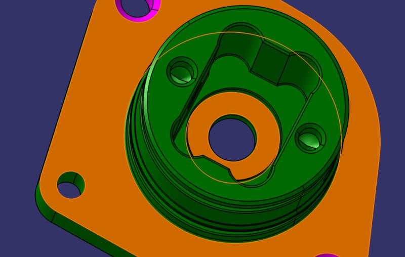
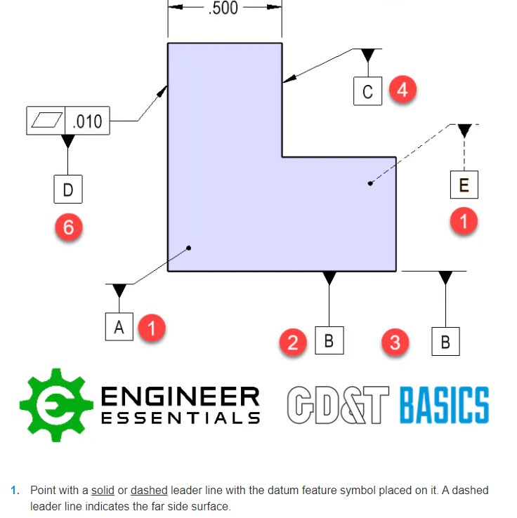
It's time for me to revisit my old friend, the square symbol. The star shaped bar is a torque-transfer mating interface for a BLDC actuator.
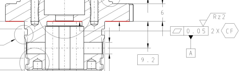
Parallel planes are 7.44 mm at the given distance (there's a measuring section plane not shown). I want to get lazy and not dimension everything. Can I square symbol this, with CF attached? I don't see a problem with it. ASME lacks in giving examples of square like features where this could be applied.
Also, the entire star shape is tapered by 0,5° between planes. How to adress the profile if I want to control the 3D surface not just a section of it? (Theoretically, because I don't want to increase CMM time and quality costs)
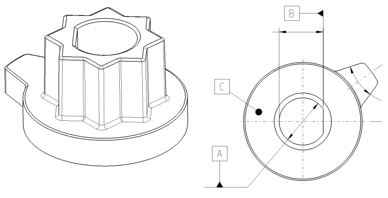
DRF picture
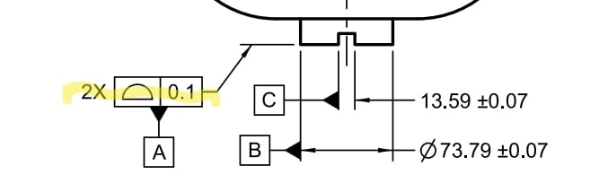
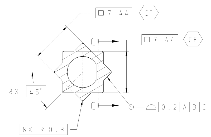
Square tolerancing
It's time for me to revisit my old friend, the square symbol. The star shaped bar is a torque-transfer mating interface for a BLDC actuator.
Parallel planes are 7.44 mm at the given distance (there's a measuring section plane not shown). I want to get lazy and not dimension everything. Can I square symbol this, with CF attached? I don't see a problem with it. ASME lacks in giving examples of square like features where this could be applied.
Also, the entire star shape is tapered by 0,5° between planes. How to adress the profile if I want to control the 3D surface not just a section of it? (Theoretically, because I don't want to increase CMM time and quality costs)
DRF picture
Square tolerancing