Continue to Site

Eng-Tips is the largest engineering community on the Internet

Intelligent Work Forums for Engineering Professionals

  • Congratulations KootK on being selected by the Eng-Tips community for having the most helpful posts in the forums last week. Way to Go!

Is it possible make kinematic without dmu kinematic and how? 1

Status
Not open for further replies.

Dialga1

Mechanical
Jan 1, 2023
15
I see some work in youtube but I don't have any idea. How they do that? Is there any methods for this I want to make in a basic die.
 
Replies continue below

Recommended for you

You use Assembly constraints to restrict translation/rotation. You can then use the compass (holding Ctrl-key down to respect the constraints), or the "Manipulation" function (tick the box) to move the parts according to the free DoF...

regards,
LWolf
 
Thank you for answering @LWolf.

In this link as you can see I see this one and I want to do like this. He said in comment is without dmu


We can move like this ur right but want like animation looks like this video.

And also Am I wrong this channels name looks familiar but not sure.
 
You can find Tiago in the forum, maybe you can drop him a message and ask directly.
 
You can do it with DMU Navigator. Search for videos .
 
I,

I have just now see this thread.

In the past i have created this. For when we don't have DMU kinematics at disposal, we need to make some workarounds. I wanted to make sure all tooling kinematics worked as I planned, so I needed to think out of the box.

I can make some general explanation of the work flow.
Create a new Product, where you will put all of your assemblies. Lower part is rigid, lifter, pad, upper tool, one product each, and if you have any other components with other kinematics, than you need another assemblies.

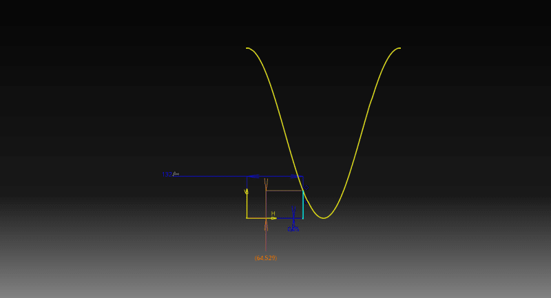
First you need to have the curve of press's kinematics. Remember that the press will be the "motor" of your kinematics. So for a defined press angle, you will have an height for the upper part of tool.

R5pUPflWSj_b4v600.png

In this case, your press angle is 132º, and the height is 64.529 mm.

So you have your first constraint. You will constraint the upper part, with lower, with an offset constraint, where you will link the distance to the sketch offset distance. Now if you change the angle, your height will update accordingly.

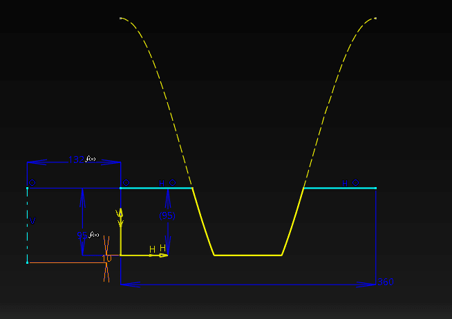
For the lifter same thing. in this case, you will need to cut the curve, according to your lifter stroke.

s07q6eu10O_ybch7y.png


Some thing for blank holder, and others...

To create the animation, I have created a macro, that will export an image for each press position (each 5 degrees, or 10 degrees), then with an image, there are a few softwares that can convert images in videos.

While drawing it's not that versatile to do the videos. But very usefull to change the press angle, and understand what's going on with your kinematics. Specially if you have any cams.

Hope it helps!


Tiago Figueiredo
Tooling Engineer

Youtube channel:
 
Status
Not open for further replies.

Part and Inventory Search

Sponsor