Continue to Site

Eng-Tips is the largest engineering community on the Internet

Intelligent Work Forums for Engineering Professionals

  • Congratulations KootK on being selected by the Eng-Tips community for having the most helpful posts in the forums last week. Way to Go!

Is the 2% rule for bracing valid for concrete columns? 2

Status
Not open for further replies.

HanStrulo

Civil/Environmental
Apr 16, 2021
117
Hi Everyone.

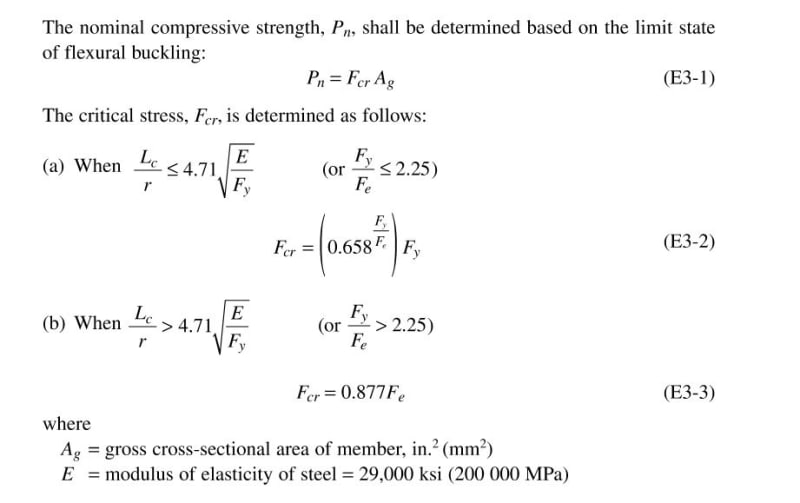
In Appendix 6 of the AISC, the strength and stiffness requirements for bracing are presented with 2% being the rule of thumb.

Is the 2% of vertical load bracing requirement also valid for concrete columns?

Do concrete columns have any special bracing requirements.

Thanks alot!
 
Replies continue below

Recommended for you

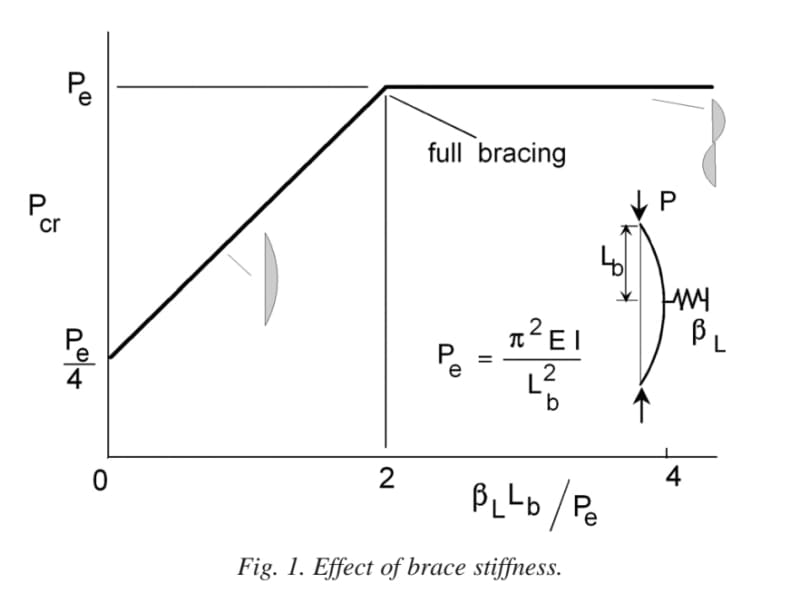
It is probably not directly relevant to the discussion here, but some time ago I did a numerical (as opposed to a theoretical) study around applying a lateral spring at the midpoint of a classical "slender" Euler column, both ends pinned.[ ] I was trying to work out the minimum stiffness this mid-height spring needed before it would force the column to buckle in what would normally be its second mode (the "S-shape") at a lower axial load than that which would induce buckling in what would normally be its first mode (the "C-shape").

The answer was a lateral spring stiffness of ~158*EI/L^3.

Someone, somewhere, will have done this theoretically, but I was (and remain) unable to find it.
 
Enable said:
...but disagree about his view on overburden; because regardless of the mechanism that supplies the work, the same work needs to be performed to deform the structure to a shape.

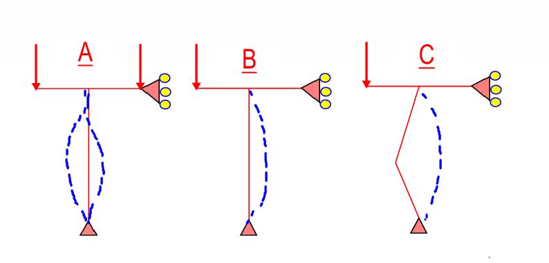
I think that there is some truth in that statement and some interesting things to unpack from it. Consider the sketches below and my reformulation of your ideas, in my own words:

For the column to buckle, the surcharge must move vertically. That motion implies that external work is done and the "cost" of buckling is altered. That alteration in the cost of buckling will alter the critical load at which buckling occurs.

I feel that statement to be true. Having pondered this a while now, I feel it simplest to consider the effect of overburden to be just additional column load: axial and bending. With reference to the sketches:

CASE A: symmetrical overburden on an "perfect" column. Here, no net moment is induced in the column and the overburden serves to do nothing other than add axial load to it. When the column buckles to the right, the leftmost overburden moves downward and sheds potential energy. At the same time, the rightmost overburden moves upward, and gains potential energy. The net, energetic effect is no effect at all other than the increase in axial load. This case is pretty trivial since perfect balance would be almost impossible to achieve in practice.

CASE B: Asymmetrical overburden on a "perfect" column. Here, the overburden creates a CCW moment on the top of the column and a "preference" for the column to buckle to the right. The critical load for buckling to the left is actually increased because of the overburden. However, the critical load for buckling to the right is decreased and, since this winds up governing the column design, the addition of the overburden has a negative impact on the column design.

CASE C: Asymmetrical overburden on an imperfect column. Here, if one could know the column's preferred direction of buckling from the outset, by way of either load or imperfection, one could strategically place the overburden to counter that as shown in the sketch below. In practice, this would be a very difficult thing to do reliably and one would have to account for the interplay of i) increased axial load ii) rectifying overburden moment iii) column imperfections. But, still, the column's critical buckling load could be increased by overburden in this fashion.

C01_rs0nxa.jpg
 
In the past, the concepts shown in my previous post have led me to ponder the following questions:

Q1) When we do the code axial, buckling load check on a beam-column, why do we not include the effects of moments on the column which would encourage buckling?

Q2) How is it that the same members tying into a column that deliver buckling encouraging moments to it can simultaneously be considered rotational buckling restraint? Surely a thing cannot be load and restraint simultaneously?

These are my answers to those questions:

A1) We do consider the effect of moments on column buckling but we include them in the flexural design term of the beam-column interaction equation as moments amplified by axial load. This still strikes me as odd because it means that we're combining two different methods of stability evaluation: bifurcation in the axial load check and moment magnification in the flexural check. I get that they are related but it still feels a bit "apples and oranges" to me.

A2) A member cannot, indeed, be both load and restraint at the same moment in time. Rather, a member may start off as a buckling encouraging load and then, through the process of buckling motion itself, shed that loading function and transition to a state of joint restraint. To my knowledge, this temporal aspect of things is not addressed in our code beam-column design provisions.
 
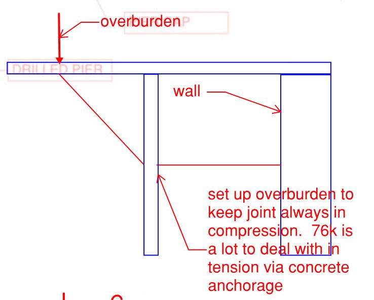
This is just me having fun trying to dream up a practical application for strategic overburden.

C01_xtshqg.jpg
 
KootK said:
A1) We do consider the effect of moments on column buckling but we include them in the flexural design term of the beam-column interaction equation as moments amplified by axial load. This still strikes me as odd because it means that we're combining two different methods of stability evaluation: bifurcation in the axial load check and moment magnification in the flexural check. I get that they are related but it still feels a bit "apples and oranges" to me.

Is there bifurcation in the axial check? Or is it approximate moment magnification that happens to make use of the Euler result? For steel, some of this appears as a reduced axial capacity as a bit of a fudge, but concrete design doesn't do that (unless you make it by producing slender interaction curves to compare to first-order results). I'm not sure either is bifurcation though.


KootK said:
A2) A member cannot, indeed, be both load and restraint at the same moment in time. Rather, a member may start off as a buckling encouraging load and then, through the process of buckling motion itself, shed that loading function and transition to a state of joint restraint. To my knowledge, this temporal aspect of things is not addressed in our code beam-column design provisions.

It all happens at the same time. I think of it as different response to different actions (applied load response vs p-delta response), but the different actions are just a model for understanding. Overall, it's response to the actions in total. Say the loads applied to the column cause single curvature first order moments, but the p-delta component is reverse curvature due to fixity each end. That actually happens all at once as the load grows.
 
FYI: I've been speaking to steel design although I failed to mention that explicitly.

steveh49 said:
Is there bifurcation in the axial check? Or is it approximate moment magnification that happens to make use of the Euler result?

That winds up being a whole lot of question as you would know from past threads.

1) There is bifurcation in the less practical, high slenderness range where it's pure Euler.

2) In the intermediate slenderness range, it's a curve fit, using Euler as an index parameter, to experimental data and numerical analyses. Since experimental data and numerical analyses would both include imperfection estimates, they would also both approximate moment magnification in this sense.

3) Since bifurcation and moment magnification are two different approaches to the same thing, it's difficult to imagine a case in which one wouldn't ultimately wind up being an approximation of the other, moment magnification being more representative of the real world phenomenon.

4) I was thinking more in terms of what a designer actually does, computationally, when checking for axial alone. Moments simply do not enter into the procedure explicitly. As a result, the designer has no moment to magnify at this step. To the extent that moment magnifications enters into it:

a) It's present elsewhere, in the flexural term of the interaction equation and;

b) It's built into the curve fit equation in a sense but not in a way that reflects the actual end moments on the column. That would seem to be left for [a]. At this step, larger end moments aren't leading to greater moment amplificatoin.

C01_stt0ya.jpg
 
steveh49 said:
It all happens at the same time. I think of it as different response to different actions (applied load response vs p-delta response), but the different actions are just a model for understanding. Overall, it's response to the actions in total. Say the loads applied to the column cause single curvature first order moments, but the p-delta component is reverse curvature due to fixity each end. That actually happens all at once as the load grows.

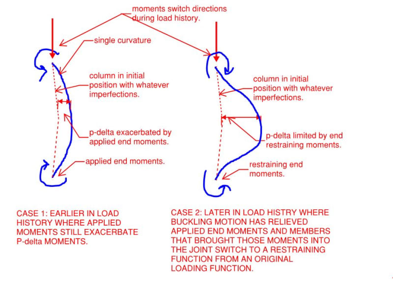
1) I disagree. That said, if I'm wrong, I would definitely like to get straightened out the matter.

2) I've attempted to tell the story of your hypothetical, single curvature column from my perspective. What am I missing?

C01_prnbtw.jpg
 
We probably just think differently and describe it differently. I see that as a non-linear load effect overtaking a linear load effect. Although we're considering a load increasing over time, the time isn't the factor: it could happen over a minute or a month with the same result.

Also to clarify a previous comment: when I said it all happens at the same time, what I meant was that first-order moments don't exist outside analysis. The real structure doesn't experience them.

KootK said:
I was thinking more in terms of what a designer actually does, computationally, when checking for axial alone. Moments simply do not enter into the procedure explicitly. As a result, the designer has no moment to magnify at this step.

I see that as a step on the way to the interaction check, though it is used as a standalone check in Australia (steel) for a specific circumstance. The Australian method is similar to direct analysis and has been for 30 years (I now know), except we don't reduce the nominal stiffness. Because of this, we still need to satisfy a check of just the axial load (ignoring moments) with the effective length factor >1.0 where applicable. This is to catch cases where the analysis moments are low, so the axial load can be high.

The step of capacity reduced by effective length is missing from concrete design AFAIK. How much of an issue that is is something I'd like to understand better, or rather when it's an issue.
 
steveh49 said:
Also to clarify a previous comment: when I said it all happens at the same time, what I meant was that first-order moments don't exist outside analysis. The real structure doesn't experience them.

Would it be accurate to rephrase that as: the real structure does experience first order moments but always in conjunction with second order moments occurring in tandem?

steveh49 said:
Although we're considering a load increasing over time, the time isn't the factor: it could happen over a minute or a month with the same result.

I don't understand what you're getting at with that. Whether a structure goes from unloaded to buckled hopelessly over a month or a microsecond, so long as the progression occurs over some time interval, that time interval can include transitions from certain states of being to other states of being.

steveh49 said:
We probably just think differently and describe it differently. I see that as a non-linear load effect overtaking a linear load effect.

Sure, but as you've pointed out, both non-linear and linear effects are acting at all times. Do you not agree, in the case of the scenario shown in my previous post, that there is some point in the history of the net loading condition, proceeding from no load to buckled, where the net moments at the ends of the columns transition from:

1) CCW at the top and CW at the bottom, both serving to exacerbate P-delta effects to:

2) CW at the top and CCW at the bottom, both serving to restraint P-delta effect?

If you agree with that, then it seems to me that you would also have to agree that there is no point in the load history where both #1 and #2 are true concurrently.

 
KootK said:
Would it be accurate to rephrase that as: the real structure does experience first order moments but always in conjunction with second order moments occurring in tandem?

That's the mathematical model, but the reality is the total.

KootK said:
I don't understand what you're getting at with that. Whether a structure goes from unloaded to buckled hopelessly over a month or a microsecond, so long as the progression occurs over some time interval, that time interval can include transitions from certain states of being to other states of being.

KootK said:
To my knowledge, this temporal aspect of things is not addressed in our code

I was responding to the second (earlier) quote here. Time-dependent effects aside, it's related to load level and independent of time, so I don't consider it a temporal aspect.

KootK said:
1) CCW at the top and CW at the bottom, both serving to exacerbate P-delta effects to:

2) CW at the top and CCW at the bottom, both serving to restraint P-delta effect?

If you agree with that, then it seems to me that you would also have to agree that there is no point in the load history where both #1 and #2 are true concurrently.

I agree that the total moment can't act in two directions at once, but the rest of it is just how an individual thinks about it (ie their model). At stage 2, is the moment restraining the P-delta effect, or is it the P-delta effect itself? And has the exacerbation disappeared, or do you still consider it present because the 'restraining moment' at stage 2 is less than it would be in the absence of the first-order moment? That last question has to put aside the thought that the moments might not reverse if the original moment were smaller because the P-delta effect would be smaller...
 
steveh49 said:
That's the mathematical model, but the reality is the total.

I feel that what I described in my restatement was the total.

steveh49 said:
Time-dependent effects aside, it's related to load level and independent of time, so I don't consider it a temporal aspect.

I disagree. Load level itself is a function of time. Most of what we do as structural engineers is predicated up loads being applied slowly. Triangular external work diagrams and all that jazz. And that, obviously, implies a time dimension. If we're talking about instantaneous loading -- effectively impact design -- that's a whole other kettle of fish. In the context of what we've been discussing, the condition at any point in time is independent of the load history path taken to get there. But that doesn't preclude there being meaningful states of transition along the way.

steveh49 said:
I agree that the total moment can't act in two directions at once, but the rest of it is just how an individual thinks about it (ie their model).

I feel that there are straightforward answers to the questions that you've raised that are, in fact, perspective independent. I'll give that a go now. I feel that it is much more useful to speak of rotational stiffness at the joints rather than the moments applied at those joints although those things are clearly related.

steveh49 said:
At stage 2, is the moment restraining the P-delta effect, or is it the P-delta effect itself?

At stage 2, the rotational stiffness afforded to the column end joints by the surrounding structure has been mobilized to preclude a single curvature mode of buckling and, instead, force a double curvature mode of buckling. At this stage, there are two, equal, opposing moments acting at the column end joint, in equilibrium:

1) The moment generated by the P-delta effect within the column and;

2) The moment generated by the structure surrounding the column joint having rotated as required to put the joint in rotational equilibrium.

steveh49 said:
And has the exacerbation disappeared, or do you still consider it present because the 'restraining moment' at stage 2 is less than it would be in the absence of the first-order moment?

It kind of depends on what we're calling the "exacerbation".

3) The column lateral displacement generated by the first order moments during phase one remains, baked into the future buckling cake in phase two as it were. I see this as, fundamentally, why a column with an end moment buckles at a lower load than a column without such a moment: the end moment adds to the destabilizing impact of other perturbations.

4) In phase two, the surrounding structure ceases to contribute additional, exacerbating moment to the column end. Quite the opposite: the execrating moments at the column end gradually dissipate to zero en route to eventually taking on a restraining role in phase two. The exacerbating column displacement doesn't dissipate though. Instead, it is maintained, and exacerbated further, by the ever increasing impact of the P-delta effect.

3) This notion of "restraining moment" is causing confusion I feel. Going forward, I'd like to ditch that and, rather, discuss things in terms of restraining, rotational stiffness at the column end joint. Restating previous statements in that vein:

a) The rotational joint stiffness at the column end joint is present, at a constant magnitude, throughout the entire load history of the column. Phases one and two, no load through collapse.

b) In phase one, [a] presents as a column end moment that displaces the column laterally and thus exacerbates P-delta instability.

c) In phase two [a] presents as a column end rotational restraint that prevents single curvature buckling and, instead, promotes a higher mode of column buckling (double curvature etc).

It may be helpful to think of phase one as the portion of the load history during which the column is still "considering" buckling in single curvature. It hasn't yet "discovered" its rotational end restraint. The transition point between phase one and two is where the column buckles in single curvature and subsequent lateral movement of the column engages the end rotational restraint required to force a higher / double curvature buckling mode.

steveh49 said:
That last question has to put aside the thought that the moments might not reverse if the original moment were smaller because the P-delta effect would be smaller...

If conditions are such that the moment never reverses, then the rotational stiffness at the the column end joint provided by the surrounding structure is insufficient to brace the column and the column buckles in single curvature, with the surrounding structure participating in that buckling.. In this situation, phase two is moot because the system never gets to the transition point.

 
If we are to continue this discussion:

1) We need more sketches and;

2) I'd like to work with a model that strips away as much extraneous stuff as possible.

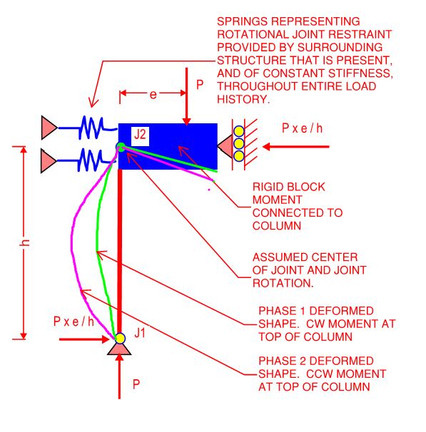
To that end, I propose the model shown below. I've attached the PDF document for download should others wish to use it in support of their own arguments.

C01_vxwfug.jpg
 
Main points in bold

KootK said:
I disagree. Load level itself is a function of time.

But for the static assumption we make, the exact function of time doesn't matter. The load does.

KootK said:
At stage 2, the rotational stiffness afforded to the column end joints by the surrounding structure has been mobilized to preclude a single curvature mode of buckling and, instead, force a double curvature mode of buckling.

Yes, if it gets that far. Namely, for the specific criterion of column end moment, the second-order effect overtakes the first order effect.

However, at every step of the way, the second order effect is reducing the column end moment compared to the first-order value. And also reducing the mid-height moment compared to a pin-end column with eccentric load. The zero-crossing of the end moment is fairly arbitrary.

KootK said:
4) In phase two, the surrounding structure ceases to contribute additional, exacerbating moment to the column end. Quite the opposite: the execrating moments at the column end gradually dissipate to zero en route to eventually taking on a restraining role in phase two.

The load increment is being delivered via the joint including first-order moment in our model, so its stiffness continues to exacerbate to some degree IMO (matter of perspective). The zero-crossing is when the column has become so floppy due to the loading that it ceases to provide any restraint to the beam end. The beam moment is the same as a simply-supported beam. Reverse curvature in the column corresponds to negative stiffness from the beam's perspective, with the column inducing a sagging beam moment at the joint.

KootK said:
[5]) This notion of "restraining moment" is causing confusion I feel. Going forward, I'd like to ditch that and, rather, discuss things in terms of restraining, rotational stiffness at the column end joint.

I thought stiffness was the issue but wanted to see where the moment would lead, so no argument.

KootK said:
c) In phase two [a] presents as a column end rotational restraint that prevents single curvature buckling and, instead, promotes a higher mode of column buckling (double curvature etc).

I think the zero-crossing is arbitrary. It will always happen at some point if you push far enough because the second-order effect will eventually overtake the linear effect. But the mid-height moment will accelerate compared to loading regardless. There is no reduction in the moment or moment increment/rate corresponding to the zero-crossing.

In terms of whether the stiffness is beneficial or not, I would propose the criterion of whether the end restraint (shorter effective length) gives greater capacity than longer effective length but no end moment (pin connection) - assuming that the structure remains stable with pin connections. And this has been discussed before in the context of whether pin assumption is always conservative.
 
steveh49 said:
But for the static assumption we make, the exact function of time doesn't matter. The load does.

I would say that the load history certainly matters if you wish to examine the interesting things that happen along the way to the final outcome, which I do.

steveh49 said:
Yes, if it gets that far. Namely, for the specific criterion of column end moment, the second-order effect overtakes the first order effect.

If it doesn't get that far then it's a boring K=1 column and there's really nothing interesting to discuss. The notion of "overtaking" bothers me semantically. Maybe you're using at as I would, maybe you're not, it's difficult to tell. Clarifying:

1) For all of phase one, the primary beam moment and second order moment are attempting to rotate joint J2 in the same, clockwise direction.

2) During phase one, as J2 rotates clockwise, that rotation causes the initial, primary beam moment to dissipate. The spring is being unwound. So, as the second order effect continues to grow, the first order moments are diminishing, eventually to reversal. So it's not the case that the second and first order moments are racing along in the same sense and the second order moment "overtakes" the first but, rather, the first order moment withdraws from the race and, eventually, reverses.

Is this what you mean when you use the term "overtake"?

Steveh49 said:
However, at every step of the way, the second order effect is reducing the column end moment compared to the first-order value.

I disagree. For all of phase two, the secondary moment and primary beam moment are equal and opposite. That's the the only way that equilibrium at J2 can be maintained. As such, as the second order moment grows, so does the primary beam moment. For phase one, yes, the second order effect is doing the "unwinding" that I mentioned in #2 above.

steve49 said:
And also reducing the mid-height moment compared to a pin-end column with eccentric load. The zero-crossing of the end moment is fairly arbitrary.

I disagree with that as well. If you examine my last sketch, it should be apparent that the mid-height column curvature increases at all points during the progression of the load history. And, obviously, more curvature begets more moment. The second order effect:

3) Reduces the mid-height moment relative to what it would be in the absence of the second order effect but;

4) Does not reduce the absolute value of the mid-height moment. The mid-height moment just keeps growing as the load history unfolds.

In a very real sense, the column has to buckle as a K=1 column before continuing on to its later role as a K = 0.7-ish column. The end restraint that kicks in at the transition between phase one and phase two is what allows additional lateral movement to happen at column mid-heigh while still maintaining equilibrium.

steveh49 said:
The load increment is being delivered via the joint including first-order moment in our model, so its stiffness continues to exacerbate to some degree IMO (matter of perspective).

I disagree yet again. Even though column end curvatures reverse during the load history of the column, you were correct earlier in implying that the general trend of motion is constant always. Ergo each increment of additional load, at all times, produces these effects:

5) Additional, clockwise rotation of J2.

6) Additional, leftward lateral motion of all points along the column height.

The key here, I think, is to take that overall trend and parse it out into an examination of which members are doing what at any point in time. If you study the equilibrium of J2 during phases one and two, I believe that it works out like this:

BEM = Primary beam end moment acting on joint. That due to rotation of the joint.
CEM = Primary column end moment acting on joint. That due to rotation of the joint.
PD = P-Delta. Column end moment acting on joint due to eccentricity created by lateral column drift.

PHASE 1: PD(CW) + BEM(CW) = CEM(CCW)
PHASE 2: PD(CW) = BEM(CCW) + CEM(CCW)

In phase one, the beam (the "surrounding structure") is assisting the second order column effect in encouraging the clockwise rotation of J2.

In phase two, the beam is opposing the second order column effect in encouraging the clockwise rotation of J2. The second order effect alone is encouraging the clockwise rotation of J2 and the continued, leftward translation of the column between its ends.

In phase two, each increment of load is increasing the restoring, counter clockwise moment that the beam imposes on J2. That, precisely because of the negative apparent joint stiffness that you cleverly alluded to.

steveh49 said:
In terms of whether the stiffness is beneficial or not, I would propose the criterion of whether the end restraint (shorter effective length) gives greater capacity than longer effective length but no end moment (pin connection) - assuming that the structure remains stable with pin connections.

There should be no debate on that issue: the stiffness is always beneficial. That, because no matter what you assume about the end restraint, you simply do not have the option of shedding the moments. At best, you can:

1) cap the moments if cross sectional plasticization is relied upon.

2) transfer the moments to the column mid-height if if P-delta column motion is relied upon to relieve the end moments.

As always, no free lunch in Newtonian physics.
 
steveh49 said:
I think the zero-crossing is arbitrary.

You keep saying that and, frankly, it makes we wonder if you've forgotten why we're discussing all of this in the first place: to determine whether or not the beam is able to both discourage, and encourage, column buckling at the same point in time within the load history. In that context, the transition between phases one and two seems quite non-arbitrary to me in that:

1) It will occur at a discrete, discernable load within the load history of the column and;

2) It demarcates a point in the load history where the buckling mode shape of the column changes and;

3) It demarcates a point in the load history where the surrounding structure switches from contributing a destabilizing moment to the column to contributing a stabilizing moment to the column.

I never claimed that the transition point was where the mid-height column moment would magically stop increasing or anything like that. That's all you.

With respect to #2 & #3 above, I certainly understand that those are gradual processes, not instantaneous quantum fluctuations etc. Is that what you're getting at here? You don't care much about these things because they are gradual processes?

 
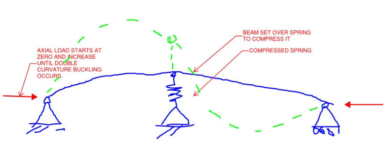
Maybe there's a simpler way to get at this. It's an imperfect analog but, with consideration to the situation shown below, would you say that:

1) The spring is offering buckling restraint to the beam at all times during the load history or;

2) The spring is a destabilizing load while in compression, and a stabilizing brace while in tension?

C01_ttegol.jpg
 
KootK said:
If it doesn't get that far then it's a boring K=1 column

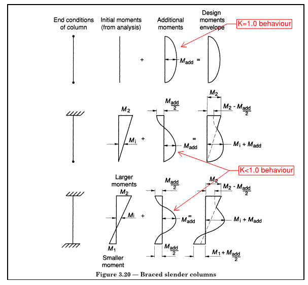
I don't agree. The second-ordee behaviour is still that of a column with restrained ends at all load levels. See image below (from the British Standard so the values are design approximations rather than exact, but the trend is there). Note that M_add is not the same is all cases as it depends on effective length, and is greatest in the K=1.0 case (all else equal).

BS8110_BracedSlender_q5ehdu.gif


KootK said:
that rotation causes the initial, primary beam moment to dissipate

That's an interpretation. In my way of thinking, primary moments can't dissipate. They are the moments you would get in a first-order analysis where only the relative stiffness matters, not the actual magnitude of the stiffness. Put another way, the members are infinitely stiff, but proportionately so. The second order analysis tells us how much ground is given by settling for real members with finite stiffness.

KootK said:
I disagree. For all of phase two, the secondary moment and primary beam moment are equal and opposite. That's the the only way that equilibrium at J2 can be maintained. As such, as the second order moment grows, so does the primary beam moment.

We have different definitions of primary moment which is no doubt hampering discussion. My definition is above. The beam, as well as the column, is subject to second order effects. The sum of beam moments (primary + secondary) equals the sum of column moments, because the primary moments are equal as are the secondary moments.

KootK said:
In phase one, the beam (the "surrounding structure") is assisting the second order column effect in encouraging the clockwise rotation of J2.

In phase two, the beam is opposing the second order column effect in encouraging the clockwise rotation of J2. The second order effect alone is encouraging the clockwise rotation of J2 and the continued, leftward translation of the column between its ends.

Individual interpretation again. In my model, the beam stiffness always benefits the column if the second order effect is isolated (see the image above). However, at low axial load and low deflection, the primary moment is the larger effect. The secondary moment becomes larger (overtakes) at some larger load.

KootK said:
3) It demarcates a point in the load history where the surrounding structure switches from contributing a destabilizing moment to the column to contributing a stabilizing moment to the column.

I don't think the distinction is worthwhile. The effect on the structure of the first load increment after the crossing is substantially the same as the last increment before the crossing. The end moment reduces but the mid-height moment still grows - there has been no more stabilisation than was already occurring. Why not draw the line at the point where the end moment is maximum, so further load reduces the end moment?

KootK said:
You keep saying that and, frankly, it makes we wonder if you've forgotten why we're discussing all of this in the first place: to determine whether or not the beam is able to both discourage, and encourage, column buckling at the same point in time within the load history.

I just remain convinced that it's a matter of interpretation. When I said earlier that the total moment is the reality, I was getting at the fact that load increase will move the structure closer to failure. We can chop that into components in different ways and label some of them as stabilising, but overall it's one-way traffic.
 
A late night thought on your question from 22 July 19:59:

Assuming elastic conditions (which I think you intended), replace the precompressed spring with uncompressed spring and equivalent force, then replace the force with an initial deflected shape (becauses stresses don't really matter for elastic buckling conditions). Doesn't that reduce to the standard bracing analysis? A spring of any stiffness provides a bracing effect. It needs to be stiffer than some value to cause the full sine shape. The spring force will be higher the more you bent the beam over the spring to start with.

In practice with finite beam strength, you might break the beam more due to the initial due to transverse load than due to the axial load.

Screenshot_20210724-003206_Box_arwlor.jpg
 
steveh49 said:
Doesn't that reduce to the standard bracing analysis?

1) Minor point: not quite the standard bracing analysis because that initial deflection effectively adds to the other imperfections that we normally assume.

2) Larger point: in that setup, it seems to me that you've basically arranged things such that the system would be equivalent at the transition point. In doing so, however, it also seems to me that we've moved the starting line forward in time and have lost our ability to study anything that took place before the transition point. And it's really the stuff that happens before the transition that is the stuff of our original disagreement and all that followed.

I would very much like it if you would indulge me and answer the question that I asked when I posed the setup initially: for my proposed setup, unaltered, do you consider the spring to be performing a bracing function during the portion of the load history for which the spring would be in compression and exerting a destabilizing force on the strut?

You keep telling me how everything is a matter of diffing perspectives. I set up the scenario in my last sketch in an attempt to distill the situation a bit and, hopefully, better understand your perspectiv3e. That's all for naught though if you simply answer my questions with more questions. I'm happy to answer your questions but would like mine answered as well.
 
steveh49 said:
Why not draw the line at the point where the end moment is maximum, so further load reduces the end moment?

Because that would do nothing to address the original point of disagreement which was whether or not elements of the surrounding structure can simultaneously:

1) Deliver destabilizing moments to the column end;

2) Be said to be offering rotational restraint to the column end.

For that purpose, which is the purpose, is the logical point of interest not the point within the load history where:

3) Column end curvatures pass zero and reverse and;

4) Column end moments pass zero and reverse?

 
Status
Not open for further replies.

Part and Inventory Search

Sponsor