Continue to Site

Eng-Tips is the largest engineering community on the Internet

Intelligent Work Forums for Engineering Professionals

  • Congratulations KootK on being selected by the Eng-Tips community for having the most helpful posts in the forums last week. Way to Go!

Is there a way to only get tension?

Status
Not open for further replies.

bojoka4052

Mechanical
Oct 8, 2021
108
Design 1 has a pretty even circle geometry, Design 2 has a new roof segment which is longer than the roof segment of Design 1.

In the middle there is a suface load pushing everything outwards. The structure is pinned at the bottom.

The problem is that all the bolts are supposed to be in tension due to the self weight of the roof, but with the new roof segment my bottom bolt is in compression. I tried to move it up and rotate it to be 90 degrees with the horizontal axis, but still the bolt is slightly in compression.

I am thinking this is due to the increased surface which gives higher overall surface load, which pushes the roof up so much that it does not matter where I place the bottom bolt. But on the other side I should get more self weight of the roof pushing it downwards aswell, but I guess this is not enough to compensate.

Is there any way for me to get my bottom bolt to be in tension? Would it help to add more bolts (im guessing not)? I tried rotating and placing it higher but that didnt seem to help. Would love to hear any inputs or suggestions you guys might have.
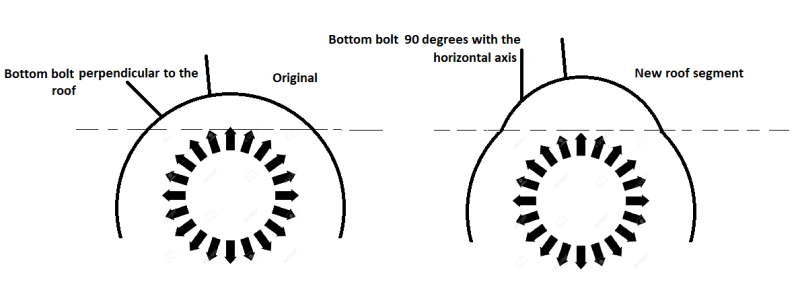
1_fhsjac.png

Left is Design 1, Right is Design 2.
 
Replies continue below

Recommended for you

I think if you want some real answers you'll need to clarify a bit.

What is this structure?

Why must the bolts be in tension?

What are the bolts connecting to the structure, or what are they connecting the structure to?

What magnitude of load are we talking about?

What's the bad outcome if the bolt is in compression after analysis?
 
What is the mechanism that makes the bolts take compression. Are they double-nutted?
 
The bolts are pinned at the top, hence why it can take compression. This is just an FE model, but its supposed to be a concrete structure with steel bolts, so im guessing there will be atleast a few hundred kilograms we are working with. Bolts arent really supposed to carry compression, but due to the pinned connection. I am wondering what would happen if I changed the connection to no longer be able to carry compression, where would all this extra compression go?
 
I afraid the situation still isn't clear. What are you connecting to what? What is the applied load? Why are you expecting only tension in the bolts? What does the connection detail look like?

go back and look at your first post, pretend you don't know what your problem is, is there enough information in that post for us to understand the situation, the goal, how things are going together, etc? I don't think so.

Better questions and information will receive better guidance.
 
I am lost too. I am not sure what "bolts are pinned at the top" means. And what about shear on the bolts? Are the arrows you show the "outward load" and the bolts are perpendicular to them?

You do need a 3D sketch at least.
 
The easiest way to answer your own question would be through a free body diagram, specifically at your bolted connection. There isn't enough information here yet to help determine a load path. Since you mentioned that this is an FEA model, it seems like you are modeling the roof to be pin supported at some interval along the edge where the bolts are. If this is case, then yes you get a reaction that looks like compression on the bolts, but that really isn't accurate.

The way I'm imagining your structure is you have the vertical concrete walls and then some flat metal roof plate sits directly on top of those walls with a vertical bolt that is embedded into the top of the wall and is fastened the flat roof plate down. In this case all of the gravity loads bear directly onto the concrete walls. You mention the structure is concrete; is the roof concrete as well? If so what are you bolting together? Again, a picture or more description would help clarify.

The bolts would only be engaged in tension if something (like wind) pulls directly up on the roof while the wall takes the compression from gravity loads. And of course, don't forget to design your bolts for shear like Ron247 mentions.

 
What sort of free body diagram should I look at? Moment, force or shear?
 
A free-boy diagram is not a moment, force or shear diagram. It is a sketch of the key structural pieces of your structural system with the forces applied to it.
 
Status
Not open for further replies.

Part and Inventory Search

Sponsor