Continue to Site

Eng-Tips is the largest engineering community on the Internet

Intelligent Work Forums for Engineering Professionals

  • Congratulations waross on being selected by the Eng-Tips community for having the most helpful posts in the forums last week. Way to Go!

is this bad engineering?

Status
Not open for further replies.

dexion7

Automotive
Dec 8, 2010
26
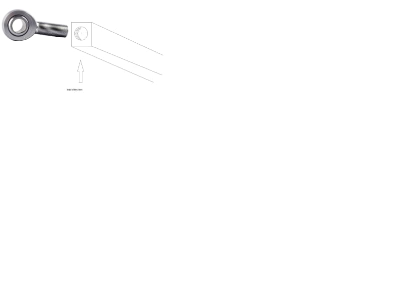
I'm planning to make a mount to support a 150kg engine from a solid 200mm x 38 x 50 rectangular section aluminum bar of which each end will have an M16 hole tapped and fitted with a rose joint, the bores of which will be bolted to the chassis. obviously there would be a washer and then a lock nut securing each rose joint.

the centre point of the bar would take the engine weight (via a rubber mount) but the torque reaction of the engine would have a tendency to try and exploit any clearance between the rose joint threads and those of the tapped holes.

obviously a rose joint is designed to work in tension but in this case there will be a load which is effectively on the side of the threads.

is this still all a bad idea or, if its ok, would a coarse thread rose joint be better than a fine thread?
rose_joint_side_load_uprtsh.jpg
 
Replies continue below

Recommended for you

As long as the threads are preloaded sufficiently by your nut, I wouldn't worry about the threads. Make sure the shank of the bearing can handle the bending and shear loads.
 
Well this snapshot makes it virtually impossible to understand what you're trying to do or where the forces are.

Why don't you drill the rose joint vertically?

It looks a bit of a weedy bar with 150 kg hanging off it.

Are you suggesting this would be used whilst the engine is running??

I can't say it's bad engineering, but it doesn't look like good engineering to me.. IMHO.


Remember - More details = better answers
Also: If you get a response it's polite to respond to it.
 
Well at the simplest level, heim joints in bending are almost always bad.

You're putting a relatively slender, surface hardened part into bi-directional bending, at a very high cyclic rate (whatever your average engine RPM is...).

I'd expect you'll have fatigue failures. This sounds like a case where catastrophic failures of this part would be, at the very least, not good.

I'd re-evaluate the use of a heim joint here. Although we don't have a lot of context to evaluate what you're doing (that's a gentle prod to tell/show us more).
 
thanks for the responses guys and apologies for the brevity of the original information.

the components are brackets (there are actually 2) which will support each side of the cylinder head of a bike engine (engine assembly includes gearbox) in a kit car. whilst I earlier said the load on the bracket is 150kg that was just a random figure for dynamic conditions so that I could get a go/no-go feel for the viability.

the engine assembly weighs 120kg and other, more conventional supports are at the bottom of the sump, diagonally opposite the cylinder head mounts that we are concerned with. most of the static load of the engine is taken by the lower mounts and I'd guess that in static conditions each of these cyl head brackets might see around 15-20kg and I'm happy with the design regarding 20kg .

the engine assembly output (i.e. after gearbox reduction) is close to the lower mounts so internal gearing within the engine would suggest that most engine torque reaction will be taken by those lower mounts and significantly less at the cylinder head area.


the 200mm long aluminum bar is positioned in a horizontal manner and is 50mm vertically and 38mm wide. each end has an m16 rose joint screwed into it and the bore of each rose joint would have an m16 bolt securing it in double shear to a typical U shaped chassis bracket.

the M16m rose joints would be good quality and are rated to have a max radial load of 80kN (there will be no axial load). the load on each of the brackets will be centrally & vertically, on the bar via a polyurethane bush. the bush design is focused upon repeatable locational accuracy rather than NVH suppression so it will only allow limited movement (perhaps 1mm) when subjected to engine torque reaction. I imagine that the less the engine is permitted to move on its' rubber mounts, the greater is the potential load on the proposed mounts?

* there is potential to increase rose joints to 20mm thread and bore
* there is potential to increase the aluminum bar to 63mm vertical and 45mm wide.
* failure would be catastrophic!


Dexion7 said:
I imagine that the less the engine is permitted to move on its' rubber mounts, the greater is the potential load on the proposed mounts?

Id say that in general terms this is correct.

Appreciate the detailed description... I guess my big question is if you're using 50x38mm bar, why a heim joint at all? Why not just drill the bar?
 
Sorry, but I really need a full drawing to understand what is going on here. words are good, but drawings are much better.

Remember - More details = better answers
Also: If you get a response it's polite to respond to it.
 

" I guess my big question is if you're using 50x38mm bar, why a heim joint at all? Why not just drill the bar? "

those joints would allow precise adjustment and repeatability of the position of the engine within the chassis which is a key requirement of the project. that's also why there would be only minor allowable movement of engine within the polyurethane bushes. the heim joints would also accommodate imperfections in the fabrication and positioning of the U brackets on chassis and would ensure that the aluminium would always present a perfectly horizontal mounting point at each end of the head.

when you say 'drill the bar' what precisely do you mean? i.e. drill the bar and then what?
 
Have you done a free body diagram to understand all the forces and directions of the forces?
 
Have you done a free body diagram to understand all the forces and directions of the forces?

no, I'm not familiar with such things. Is there insufficient detail in my above posts?
 
dexion7 said:
when you say 'drill the bar' what precisely do you mean? i.e. drill the bar and then what?

Create the mounting hard point in the bar itself.

I get where you're going with regard to adjustment, etc - but based on what you've described so far, it appears that the heim joint is an unnecessary complication.
 
Sorry but the picture shows a few parts and pieces that is all. I would need to see the whole picture of how the fitment of everything is supposed to be.
Many times in designing something like this people think there is some huge weight savings using aluminum. Not always so, using a steel tube maybe stronger and as light.
We need the big picture.
 
Status
Not open for further replies.

Part and Inventory Search

Sponsor