Eng-Tips is the largest engineering community on the Internet

Intelligent Work Forums for Engineering Professionals

Is this Corrent?

Status
Not open for further replies.

VN1981

Aerospace
Sep 29, 2015
186
0
0
IN
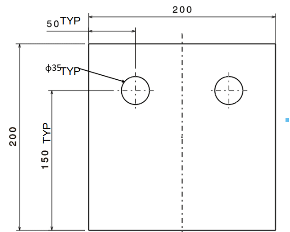
We received a drawing from a vendor...the drawing below is just for illustration of what I wanted to ask

Capture_mu3eku.png

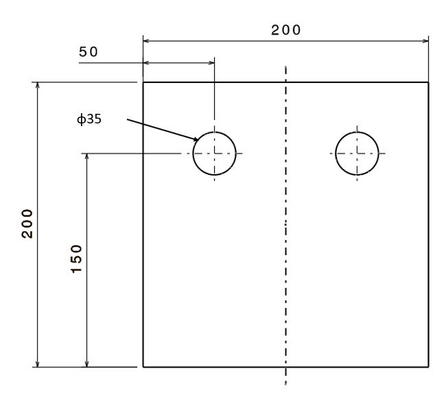
I noticed the hole on the right is not dimensioned...he explained that since he has drawn a centreline in the middle (I forgot to dimension it), it automatically means that all dimensions to features on the left applies to the other side of centreline. I've not come across such a convention...I did some cursory check online and I am not able to find any references which say such a representation is allowed. I will go through ASME Y14.5 in detail but was hoping to get some opinions from experienced engineers.
 
Replies continue below

Recommended for you

Within the practices covered by ASME Y14.5, there is a way to dimension half of a symmetric geometry and imply that the other side is mirroring the dimensioned features. But this is done differently than in the vendor's drawing - with specific symbology and only with half of the part shown, as in the following image:

Screenshot_20230624_122640_Drive_pznwwy.jpg


Without using the above mentioned-method, adding "2X" before the relevant dimensions in the vendor's drawing would resolve the ambiguity.
 
^^Burunduk, I made an omission in my drawing. All the hole dimensions include TYP call-outs. So it seems like above method is indeed allowed within ASME regulations.

Capture_mu3eku_fsxcj4.png

I added TYP texts in Powerpoint...thus the misalignment

Thanks for your reply
 
In many cases the outer boundary of the part does nothing, except holding the matter in place. A 100 between the holes would be better most of the time (except when said plate is locating sg. on its longer face)
 
VN1981,

The drawing is crap, but I can interpret it.

If he applied tolerances, he probably see the folly of dimensioning symmetrical holes from the outside.

--
JHG
 
I agree with everyone above. TYP is not a standard notation, so it is ambiguous. I've worked with enough people that do this, and when they explain it the same way as the vendor. Since they explained the symmetry thing, just go with that. But refer to @drawoh in the first sentence for the complete summary.
 

Adjective
TYP

(engineering drawings) Abbreviation of typical: used to label a feature that is to be interpreted as exactly the same as nearby comparable features.
Four equally spaced bolt holes on a bolt circle can be dimensioned at one hole with the notation (TYP) following it.

Usage notes
TYP is deprecated in current standards (such as ASME Y14.5 2009) in favor of specifying a number of places, such as 4X.
However, it's still used: and for example.

Normally it is used on minor features but, as in the above examples, some don't limit it so.
 
Didn't want to create another thread for this. ISO 2768 gives guidelines on tolerances for linear & angular dimensions. Is there an equivalent standrard available in ASME?
 
B4.3 is legacy. Not even ANSI/ASME anymore. “This standard is no longer an American National Standard or an ASME-approved standard. It is available for historical reference only.”
 
I am not necessarily looking for an ASME document providing tolerance ranges for metric dimensions...want reference of an ASME document giving ranges even for English units is fine.
 
VN1981 said:
I am not necessarily looking for an ASME document providing tolerance ranges for metric dimensions...want reference of an ASME document giving ranges even for English units is fine.

There was never such a standard for inch drawings. The common way to specify general plus-minus inch tolerances is to have a table in the title block or somewhere on the drawing that lists tolerance values depending on the number of decimals in the specified dimension value. Neither method (standard or custom general plus-minus tolerancing) is good practice anyway. You should determine your tolerance values individually according to functional requirements and manufacturing limitations.
 
I agree with others, the drawing is crap and you should tell your vendor so. People who dimension like that are lazy and think they understand tolerancing, manufacturing, or mechanical things but they really should be in another industry.

If the part is symmetrical it's unwise to dimension only one hole like that from the edge of the part because 99.9‰ of the time it's the hole-to-hole that matters. Also, if he were to use positional tolerancing with that how would he maintain symmetry which I'm pretty sure is the design intent?
 
I agree with others here. I have said before, drawings are not good anymore, just crap. People think what looks good to them, it must be good.
Good drafting practices are history, in most cases.

Chris, CSWP
SolidWorks
ctophers home
 
Status
Not open for further replies.
Back
Top