Continue to Site

Eng-Tips is the largest engineering community on the Internet

Intelligent Work Forums for Engineering Professionals

  • Congratulations waross on being selected by the Eng-Tips community for having the most helpful posts in the forums last week. Way to Go!

Is this even possible? 1

Status
Not open for further replies.

Fumunderdog

Mechanical
May 24, 2018
3
Is it possible to design a system of multiple, independently rotating, concentric (up to 9 shafts)? The inner most shaft must be at least 75mm dia and the rpm between each layer will be 125 at the peak. Leaving out manufacturing and tolerancing difficulties for now, are there any ways to accomplish something like this other than putting a ball bearing between each layer? Has anyone seen similar builds?

Any insight would be appreciated.

Thanks
 
Replies continue below

Recommended for you

Most anything is possible if properly engineered. :p

Sure, 125 rpm isnt much so I'd look into either plain bearings (ie bushings) between each shaft or simply make the shaft out of a material capable of acting as its own bearing such as grey iron.
 
I can think of a pretty common system of three independent concentric shafts, although the layer difference is smaller (roughly 1 rpm and 0.0167rpm between layers)

 
Making alternate shafts out of steel and brass might work reasonably well too - or simply going for all-brass if you don't need continuous motion.

I'm assuming it's going to end up looking like this device.

A.
 
How good of sealing do you need? Using brass or even babbitt sleeve bearings will handle a lot of load at slow speeds

= = = = = = = = = = = = = = = = = = = =
P.E. Metallurgy, Plymouth Tube
 
You see similar but much higher speed systems inside some Gas turbine engines, but 9 independently rotating shafts?

That sounds like a big ask.

what sort of length between bearings etc and thickness of the individual tubes are you looking at?

A sketch would help a lot as well.

Remember - More details = better answers
Also: If you get a response it's polite to respond to it.
 
Plain bearings were the first alternative that came to mind, I just worry about the durability and maintenance of such a system. A little more information about the machinery in question:

The center shaft will be driving a large diameter cantilevered carousel, each concentric shaft from there on would be used to drive individual elements that ride along the outside of the carousel. These individual elements (8 total) need to be accelerated and decelerated as they rotate with the carousel for process purposes. Currently this is done with a traditional mechanical cam and link design but I am looking for something with greater flexibility and quicker size change. Each of the outer shafts would be driven independently so that the cam can be done through the program instead of mechanically. We've had success with this concept for a 2 shaft system, but that was done using a right angle gearbox designed for such an application and is not available in enough sizes to accommodate 7 more shafts.

In case you are wondering, as I was the first time I saw this, the only reason the carousel itself is spinning is because the outer races that the 8 elements ride along wear too quickly if it is stationary.

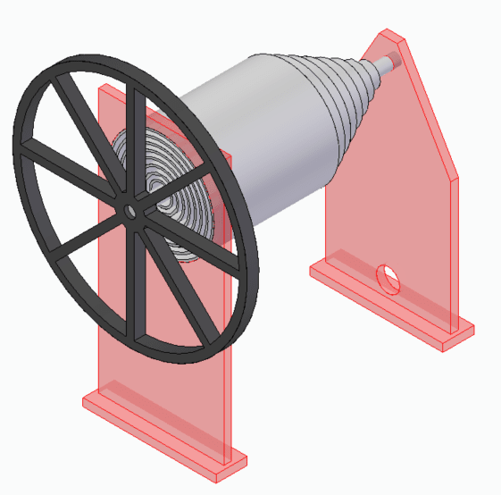
Here is a quick 3D cartoon I made to help with visualization. The elements along the carousel are not shown, nor are the links between them and the outer shafts.

image_mka498.png
 
Fine. You have them going in (near-concentric) circles.

Now. You need a series of thrust bearings to prevent shaft movement axially. Could even be friction bearings (sleeves or collars, but shouldn't be) since there will be some slight net movement.

Lubrication is far more serious: Force oil into the center of the smallest shaft, then vent it consequently through each larger shaft so all get some flow? Put the oil relief holes at opposite ends of each shaft set from the previous so lube will go through the entire wall of the entire set. STill need seals at the open end. Heat and friction will kill the process unless there is very, very little weight and load.
 
how does the inner shaft drive the outer ones ?

how does the system respond to the dynamics, of starting and stopping high (rotational) inertia loads ?

another day in paradise, or is paradise one day closer ?
 
While this can work (depending on loading) what is the goal? Is that a hand wheel? What scale are we talking about?

I have the same question as rb1957, what is driving what.
 
Thanks for all the responses and insight, truly appreciated. That 3-d cartoon is missing a lot of detail that I didn't have time to put in so I'll do my best to describe what is missing for now and maybe I'll go back and add some detail to the model if I find the time.

Scale: The inner most shaft is shown at 75mm dia (based off of the unit I am looking to replace) and the outermost layer is 675mm dia.

Drive: Each layer of this system will be driven independently which is why they are tiered on the back end. Each layer will get its own belt drive to a servo for independent control (to allow for fully programmed control of the cam).

Linkage to the elements on the carousel: The individual elements residing on the perimeter of the carousel and the linkage to the concentric shafts are not shown, but the idea is to accelerate and decelerate them as they rotate along with the carousel, which will rotate at a constant rpm. So if you imagine the carousel is running at 0 rpm the concentric shafts would simply oscillate back and forth.

Roller element bearings: This is what I first envisioned for the system but in my searching I was unable to find bearing that would be large enough in diameter for the outer layers, small enough profile to avoid adding excess girth to the overall assembly, and rated above 125 rpm. If anyone has suggestions for a supplier or product line I'd be all ears.

Once again thanks for taking the time to read and comment, always great to hear someone else's perspective.
 
Kaydon and National Precision Bearing make some pretty thin profile slewing rings.

Alternatively, I had an application where I considered using plain balls captured in a square channel (would have been similar to an o-ring groove) to make my own low-load, low speed bearings, which is what it sounds like you have here. On the other hand, I never actually did it.

Engineering is not the science behind building. It is the science behind not building.
 
Status
Not open for further replies.

Part and Inventory Search

Sponsor