Continue to Site

Eng-Tips is the largest engineering community on the Internet

Intelligent Work Forums for Engineering Professionals

  • Congratulations IDS on being selected by the Eng-Tips community for having the most helpful posts in the forums last week. Way to Go!

IS THIS MOTOR FAILURE OR PROTECTION FAILURE 2

Status
Not open for further replies.

341968

Electrical
Sep 20, 2003
31
Dear All,
One of our plant motor has recently Burnt. It was newly installed and within 8-months even not being in continuous operation (Operating in duty cycle on/off).
Motor rating: 400Vac 50Hz 36A 18.5KW 1465rpm Cos phi 0.84
The operating conditions for this motor were same as of original existing motors that is balanced three phase power supply without any harmonics, no overloading (electrical or mechanical), ambient temperature less than mentioned on motor data sheet and name plate(+50°C).
Our Maintenance department has the following assessment:
1. Motor quality was not as the existing original motors.
2. The original motor Insulation class is F/F. While the burnt motor Insulation class is F/B. That is Insulation class F but limited to temperature rise of class B. (Motor data sheet).
3. The Type of newly supplied motor is D5C while the existing motor has type D4C. Same difference exists in their serial nos. (Manf. Confirmed motor is same but with new series).
4. The motor was supplied without any QA/QC, test certificates, performance curves, and conformities.
5. No factory acceptance test or third party inspection was made/involved.
6. Considering new motor from factory no tests were conducted by our maintenance department and motor was directly installed.
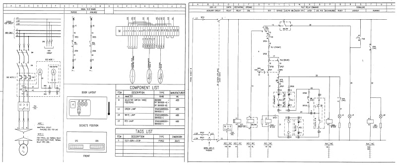
7. The RTDs in the motor were not connected to any PTC relay. As in original motor starter this option is not available. (Motor Starter Wiring Diagram).
8. The newly supplied motor had insulation failure specially the place of embedded RTDs. Two phase winding were shorted.
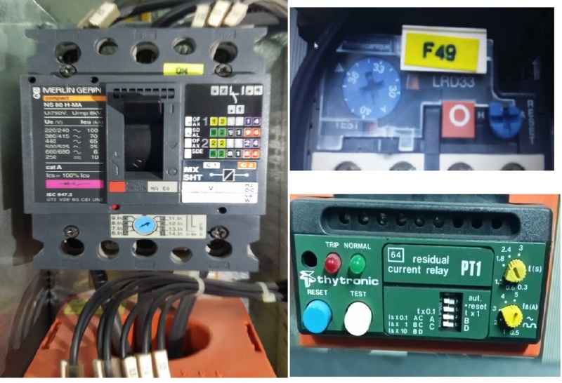
9. Protection system worked, the only short circuit by the MCCB found tripped and earth fault relay found tripped.
Could you please identify the true cause of stator winding flashover, and recommendation,
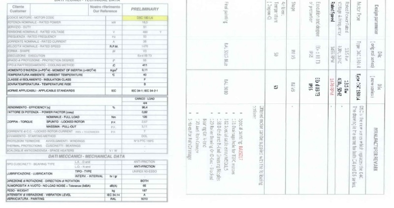
MOTOR_DATA_SHEET_e1ueur.jpg
shall be highly appreciated.
Please feel free to ask any further details you may require.
Best Regards
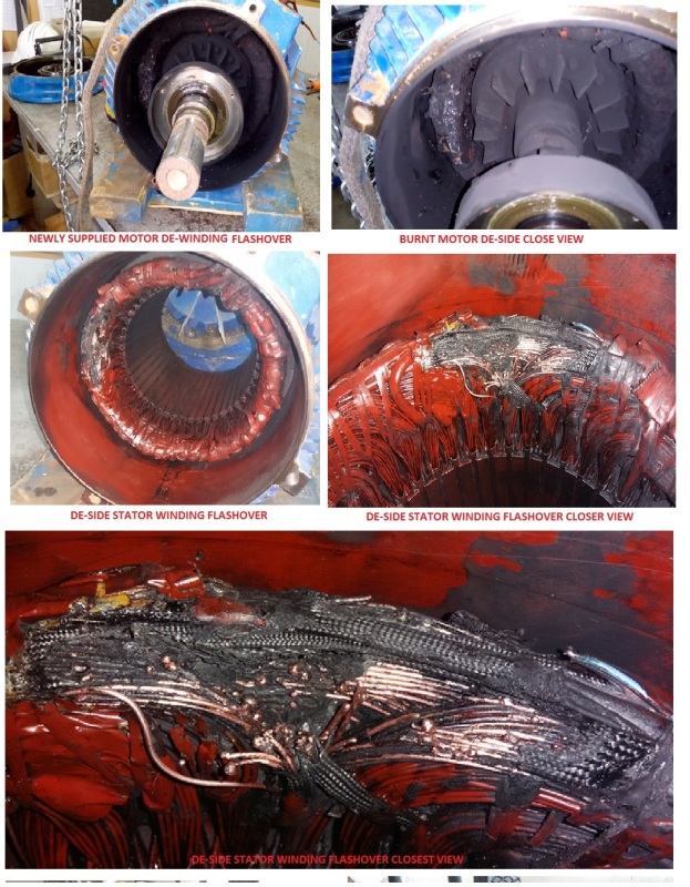
STATOR_WINDING_FLASH_OVER_vgmnqu.jpg
STARTER_WIRING_DIAGRAM_jikicf.jpg
MOTOR_PROTECTION_DETAILS_u1xens.jpg
 
Replies continue below

Recommended for you

What does the motor drive?
Is the load steady or varying?
What is the normal running current or range of running currents?
In what manner did the original motor fail?
Have there been any recent changes in the plant operation? Has production been increased or the product been changed, or other changes?
Where there any changes prior to the failure of the original motor?
Particularly, given the idle periods of the motor, was the duration of the idle periods increased?
Has the time of day of the idle periods changed?
Note: We are interested in any changes in the operating program prior to the failure of the original motor until the present.
From the pictures it appears that there is no sign of overheating in most of the windings. Pictures may be misleading. Please confirm that there is no indication of overheating in the unfaulted portion of the windings.
Is it possible that an event either in your plant or in the supply grid may have caused a voltage transient?
OP said:
It was newly installed and within 8-months even not being in continuous operation
Are there any measures in place to prevent condensation from occurring during the motor idle periods?

Bill
--------------------
"Why not the best?"
Jimmy Carter
 

DEar waross (Electrical): Please see below detail:
It is fan cooler motor belt driven. It is being used to cool inlet gas from compressor.
A pitch controller is the only load varying factor. The operator monitors the inlet gas temp. and accordingly set a command…. motor to run and adjust the fan blades to some angle via a pitch controller to get maximum cooling. If he set fan blades angle 100% then motor runs at its rated amp 36A or bit more 37. The burnt motor was operating on 36/37 Amp as the fan blades runs at max. efficiency 100% max blade pitch angle.
For similar motors whose fan blade pitch angle is set at 75% runs at max. 22 AMP.
Hence swap of these motors depends on gas temp. In summer they run all and in winter some off. Their operation start/stop is manual by control room operators.
The original motor had a rotor run out that is slight rotor bend. Due to a high tension belt and long idle condition. It was rubbing against Bearing inner cap. Thereby violating the clearance. As these motor are used in hazardous area Zone -0, So we replaced it by new motor. The old motor worked for 15-years with normal PM and routine overhauling.
These motors are Ex Proof, and are designed for harsh environment like ours (Gas Plant) in desert. Some of these days temp reached 48°C. In extreme winter its goes to -5°C. Humidity max reaches to 89.
Similar other motors are working under same condition for the last 15-years.
All the rest winding are clear, no sign of overheating there. Only the spot shown is affected. It was like huge spark which melted the broken conductors, blackened the drive end cover, rotor side etc. Short like welding arc.
We have our own Gas turbine generators, with very stable, balanced and clean power supply. I am sure any kind of transient phenomenon does not exist in normal operating conditions.
 
 http://files.engineering.com/getfile.aspx?folder=c69d883d-77a4-4fcd-9b36-4f3d1e45cd2d&file=ADDITIONAL_PHOTOS.jpg
In my opinion, since the damaged part it is in open position- not in a slot -it is not likely to be an overloading the cause. However, if it was not high-potential tested I don't think the overvoltage was the problem- as the rated voltage seems to be low.
I think the winding was damaged mechanically while in assemble process and withstand it-damaged-for a while.
 
Appreciate all the photos but showing multiple pictures of more than one motor, and entangling information
unrelated to each item makes this a very confusing post.

Another conflicting observation is the picture showing a cylindrical roller bearing in
a flange mount style motor end bracket. A flange mount, or “C” face motor is typically directly coupled
to the driven load and would not normally have an installed cylindrical bearing.
(What that's all about? Who knows.)

Knowing exactly how the motor is mounted on the piece of machinery would provide further clarity,
but with differing views of the stator failure; (a clean winding, a charred black winding), pictures of a clean rotor,
pictures of a painted rotor, and the photos of a “smoked” rotor, make it very difficult for the reader to know what’s -what-.

Perhaps a less than electrically "OK" motor was installed to replace a previously failed motor?

This post is a mess. Not sure what value, (if any) will be provided by anyone's opinion expressed here.

John
 
You said that the failure took place at the spot where an RTD is embedded. From the looks of the damage, I'd hazard a guess that the RTD was improperly embedded and damaged or weakened the magnet wire insulation in that spot.


"You measure the size of the accomplishment by the obstacles you had to overcome to reach your goals" -- Booker T. Washington
 
I can't identify the true cause, but it looks like a simple insulation failure due to a poor winding job. If I had to guess further, I'd agree with jraef that the wire insulation was damaged going around the RTD.

None of the protection you have can detect an insulation failure before it occurs. The ground fault relay and breaker tripping would make sense once the failure happened.
 
Dear dArsonval (Electrical), The painted rotor is the original motor rotor just shown to compare its quality with the defective motor rotor. You can see the difference the painted rotor is best quality and the unpainted one is of not good quality. plz see the photos as how they are installed in the plant to drive fan coolars.
18.5KW (the burnt motor) vertically installed
37KW motor Horizontally installed.

jraef (Electrical) Agree with your analysis thanks
 
 http://files.engineering.com/getfile.aspx?folder=23296ab3-9b36-4f73-a699-5c19d8865822&file=1.8-37KW_MOTORS_DRIVING_FAN_COOLERS.jpg
Dear All,

Soon after the first 18.5 KW belt driven motor we had similar accident, stator winding burnt of a 37KW fan cooler driving motor gear driven motor. Now I am sure the protection system for LV motor without being connected with RTDs does not see the wear and tear in the motors, insulation degradation, heating due to bearing problems, inercaps rubbing, greecing etc. Motor draws still rated amperes or even bit low, till insulation failure and overheating of winding lead it to short circuited and earthed.

Both of these two motors 18.5kw and 37kw were connected in star. Direct on line starting not VFD. they were from renounced manufacturer Marrelli Motori Italia.

18.5 KW motor was new but 37KW motor served for ten years almost in continuous operation.

The 18.5KW motor was belt driven, had insulation failure due to manufacturer defect. As many of you suspected.

37KW motor had mechanical overheating. It tripped two weeks b4 on overloading. Maint. Dept found everything Ok as they could not guess that problems are mechanical. They reset the overload and put back motor in service. two weeks later it burnt. Electrical protection could not detect and once winding overheated, two phase short circuited and earthed. it tripped all its protection along with main feeder, thereby tripping the whole MCC. I found the contactor was stuck (pressed inside), one contact was quite sparked and the bottom iron core was broken.

In conclusion LV Motor protection simply with thermal OL, residual Current Relay and MCCB (For Motors) can not detect moderate mechanical overloading/overheating, heat and losses due to wear and tear, bearing and inner caop rubbings etc.

In this case RTDs have to be connected with some PTC relay to trip the MCCB. or probably the new electronic thermal OL relays with TESYS starter might be effective.

We started monitoring the amperes of each fan cooler motors from yesterday.
if you are interested i can upload 37kw burnt motor and its protection photos.
I would appreciate if you could pass any comment on my conclusion.
Best regards
 
Simple tip. If the winding was overloaded and it failed (in the absence of OL/temperature protection), it will show as entire winding burnt. If the winding failed in only in a few places, it not overload.

Rest is all overthinking and missing the main point.

Muthu
 
yes edison123 i AGREE THE 18.5kw MOTOR HAD A MANUFACTURER DEFECT YOU CAN SEE THE 37kw MOTOR PHOTOS AS WELL. ALL WINDING BURNT HEAVILY TWO WINDING SHORTED AND EARTHED.
MCCB DIN NOT TRIP, RESIDUAL CURRENT RELAY DID NOT TRIP, THERMAL OVERLOAD TRIPPED.
RESULT IN FEEDER TRIP.
 
 http://files.engineering.com/getfile.aspx?folder=13fdee15-6981-402e-9e80-462ff338effb&file=37-KW_MOTOR_contactor.jpg
That stator appears to have single phasing damage and not overloaded motor damage.
 
Dear LionelHutz (Electrical),
I have two suspects here.
I found 37-KW motor Non Drive End Bearing was not free;y moving, as if some of its ball is damaged. it had a big friction at one place while rolling with hand. seems bearing damaged. It might have caused sudden high current melting of one cobtactor contact causing single phasing.
Thermal overload was tripped but contactor did not go off. It was slightly stuck/pressed inside.

Or it is the contactor Failure causing single phasing. We have tested the motor. One winding is okay. The other two winding are burnt and earthed.

So, I am still confused is this damage is caused by the bearing high friction. Or it is contactor failure.
Please if you could confirm, if it is a single phasing, the result is a damage of two winding only.
Thank you in advance.
 
I think your motor loose one phase and it working on two phases . This should be good reason for thermal overload trip and 37kW stator failure .Contactor failure and one loose contact is probable problem
Good luck
 
Dear panter (Electrical),
You are very right. Today our motor specialist open bearing upon my request. He removed the seal cover. He found small particles. flashed from winding and overheated greece. It was causing bearing hard. He cleaned the bearing and it become like a new.
So it is confirmed like your assessment, it was single phase failure. Only one thing I am surprised as one phase was missing, why the residual current relay did not trip. It is the only protection causing MCCB to trip.
 
A residual current relay won't detect a lost phase. It could have operated once the motor failed to ground but by then the damage was done and the breaker was tripping anyway.
 
Status
Not open for further replies.

Part and Inventory Search

Sponsor