Continue to Site

Eng-Tips is the largest engineering community on the Internet

Intelligent Work Forums for Engineering Professionals

  • Congratulations KootK on being selected by the Eng-Tips community for having the most helpful posts in the forums last week. Way to Go!

is this possible - cantilever RC slab 8

Status
Not open for further replies.

mats12

Geotechnical
Dec 17, 2016
181
Hello

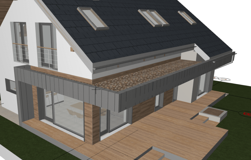
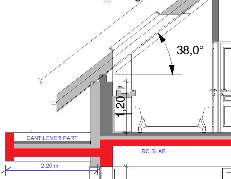
Residental building, the interior RC slab in not at the same level as the cantilever slab.
The cantilever part is non walking surface - only self and permanent load + snow load + wind load.
Can this be reinforced properly so it could work even tho slabs are not at the same level?
Dont ask why this cant be at the same level - it has to be like this acording to architect...

Thank you for help.

Brez_naslova1_up14l9.png


Brez_naslova2_zjjgkk.png
 
Replies continue below

Recommended for you

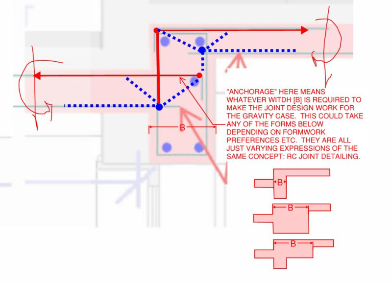
As for the detailing, it's this concept for the gravity case. Whether or not one explicitly designs the joint or just eyeballs it probably informs how aggressive / conservative they chose to be in the joint proportioning.

c02_fb96in.jpg
 
I remember someone has addressed torsion. Yes, watch out the interior beam that subjects to constant torsion from both slabs with long span. Hope the net torsional effect is nearing evened out on all occasions.
 
This would usually be a case of compatibility torsion rather equilibrium torsion. As such, the closed stirrup demand ought to be modest, at least for that purpose.
 
Interior slab will produce compatibility torsion, which usually can be ignored. I am hesitant to call the cantilever slab produces the same. One more complication is the slabs may produce torsions about different axes. Maybe I am overthinking though.

image_wg7hdw.png
 
KK, love the strut tie model, was tempted to do one.

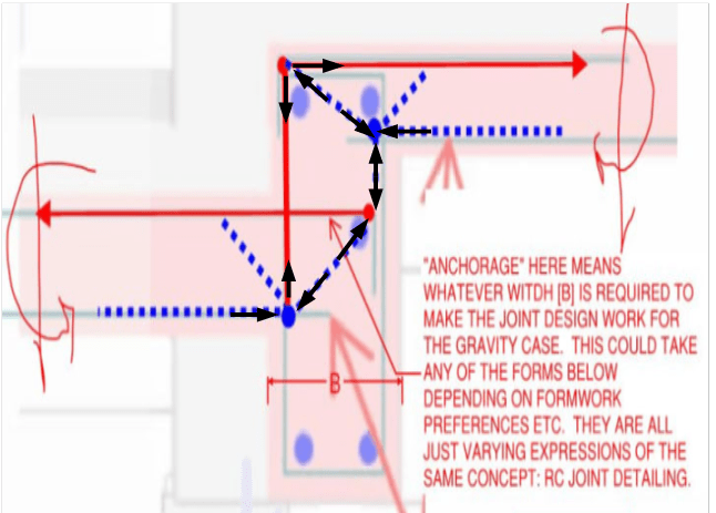
R13, refer to the strut tie model, the forces are resolved from the cantilever, without the need for a torsion beam, there maybe some compatibility torsion from the main slab.
 
The truss is in static equilibrium, but I reserve my suspicious on rotation, as the supports of the truss are not in the clear.

image_i6mett.png
 
R13, you are describing compatibility torsion as the beam will deflect but the compatibility torsion is not required for equilibrium and a designed result.
 
rowingengineer,

As you have suggested, the stem below the cantilever is not required for the consideration of torsion alone, because it does not contribute to the equilibrium. I wouldn't dire to think so. But as a note, I am not familiar with strut-tie method, except for deep beams, which has a lot of meat around the truss skeletons.
 
There is potentially significant torsion applied to the support beam at the line of facade, and the torsion is further amplified by the weight of the fascia. I'm liking the idea to frame beams/cantilever beams around perimeter of the external slab and then the external slab becomes a simple span and it can be reduced to the minimum acceptable thickness......
 
Structuring, your statement would be true if a back span wasn't present in the op design. As. Long as you can meaningful engage the back span, the torsion is only compatibility and isn't of large concern.
 
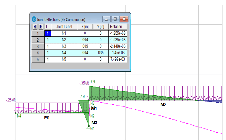
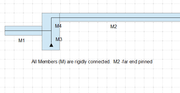
This is a simplify model of this structure in 2D. If anybody bother to look into the result, I would like to hear the opinions. Note that this model is not accurate, but I think it can provide some insight on what might happen.

Pink Line - Deflection
Green Area: Negative M; Blue Area: Positive M

image_bq4p1m.png
 
R13,
I would suggest some changes to your model.

1. M1 should be a moment carrying joint to M4.
2. M3 doesn't exist for the beam segment might be at the ends but for the problem at hand please delete.
3. Can't tell if M2 has a supply at the far end but if not please add one.
 
rowing,

Sorry, I didn't present the model with clear picture. Please indicate your suggestions again if you don't mind.

image_n4rjed.png
 
r13 your model is incorrect, you've effectively modelled a small portal frame. You need a roller at the N1 node. If you review your moment diagram this should be fairly evident, it is non-sensical.
 
Agent,

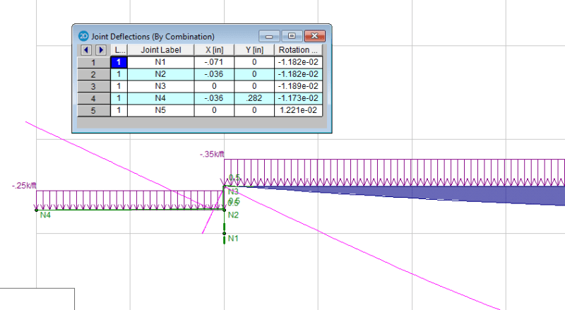
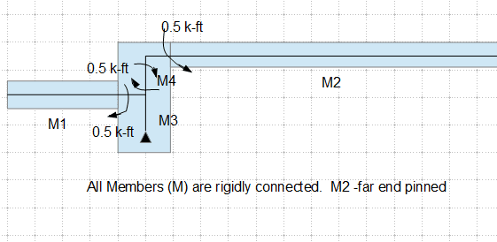
Here is your wish. I actually started with it, but thinking the beam was restrained in the far end, so changed it. Owing to the limit capability of 2D program, this model, including the previous one, is inaccurate. So all the results are indicative approximations, up to interpretation.

image_iy3f6m.png


image_kmugeu.png
 
R13,
If that is the deflection profile it is more correct.

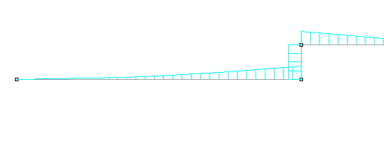
The moment profile, should look like this

moment_taahcl.png


Overall this moment profile fits the strut tie put together for the reo arrangement.
 
rowing,

Yes, you have shown the exact moment diagram at this junction.
 
Status
Not open for further replies.

Part and Inventory Search

Sponsor