Continue to Site

Eng-Tips is the largest engineering community on the Internet

Intelligent Work Forums for Engineering Professionals

  • Congratulations waross on being selected by the Eng-Tips community for having the most helpful posts in the forums last week. Way to Go!

Is this welding arrangement posible?

Status
Not open for further replies.

Jhinnie2

Structural
Sep 28, 2021
9
Hi there,


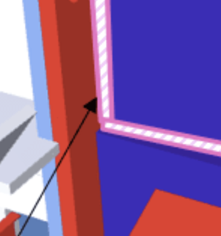
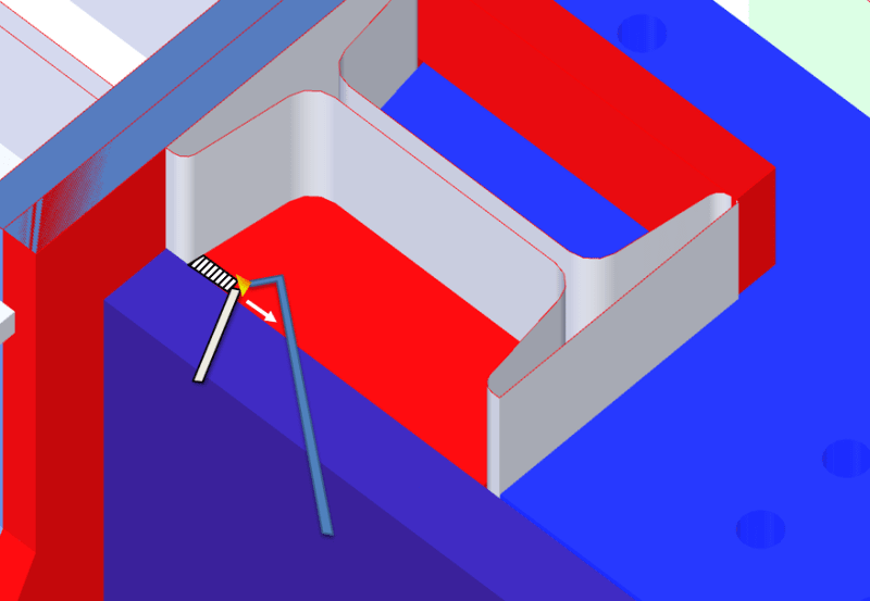
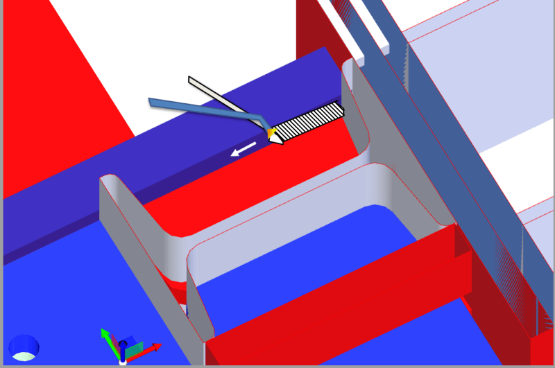
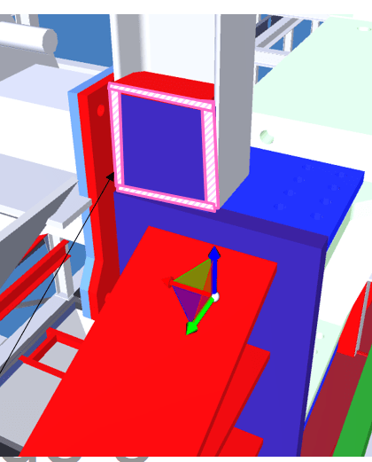
Engineer here with no experience with real-world welding so if someone let me know if this will work that would be awesome. Essentially we have a column sitffener that will be fllet welded in place, and then a big thick bearing plate will need to contact the column, and also a large beam (that is also connected to the column). Just wondering is it possible to fillet weld or potentially butt weld from one side (top face) the column stiffener to the thick end plate, say if the the end plate extends vertically 10 or 20 mm? It's quite tight in space, the column is 6" x 8" (150 mm flange width x 205 mm depth. The coumns will be boxed out, so another vertical plate will be welded on top of this thick end plate - hopefully the screenshots make sense. Other option is to extend the stiffener across the top of the thick end plate, but this would put the weld under a lot of shear rather than bearing? Thanks

Capture1_cuylmw.png
Capture2_dm6mfz.png
Capture3_ifkycg.png
 
Replies continue below

Recommended for you

Welding in to corners is problematic.

Screenshot_20220111-212815_aj12hu.png


I'm not on a boat right now but this diagram shows the lack of corners in welds. Notches and holes where welds would otherwise meet are preferable.

Screenshot_20220111-213130_binrwf.png
 
Diito TugboatEng. When improperly executed, I have seen cracks formed. I have had to develop a number of welding techniques to repair cracked welds with similar designs.
 
"Engineer here with no experience with real-world welding" ..... really ?

Why is it that I suspect that you are a STEM 3D CAD designer "with no experience with real-world engineering" ...???

I do not believe that a degreed structural engineer with steel design experience would ask this question

MJCronin
Sr. Process Engineer
 
Thanks for the 'heads up', tug... I've not experienced that type of cracking, but it's nice to know.

Rather than think climate change and the corona virus as science, think of it as the wrath of God. Feel any better?

-Dik
 
Not so germane to the OP, but Weld returns can help a lot with the fatigue resistance of a welded structure, when needed.
Ditto weld toe "improvements."
I believe AWS standards discuss details like like that.

A thoughtfully sculpted gusset might offer a markedly reduced stress concentration as well.

a few decades back some manufacturers included a curious welding "tail" detail on heavy equipment cover plate doublers and gussets.
Those same manufacturers seem to have moved to doublers artistically shaped, probably by the new guy on the CAD/FEA station.
 
 https://files.engineering.com/getfile.aspx?folder=427a6a30-8903-41e9-8202-496670db8fa8&file=weld_tails_.png
MJCronin said:
"Engineer here with no experience with real-world welding" ..... really ?

Don't worry, I meet plenty of welding engineers with no real-world welding or welding engineering experience. Some of them even have credentials!

The OP brings a legitimate question, but yes, I would encourage him/her to seek out a more experienced structural engineer.

First order of business is to separate the loading and stress concentration concerns (design) from the constructability (welding) issues. Setting aside accessibility challenges, I don't think there's anything here that cannot somehow be welded with the appropriate joint detail. Prequalified joints given in AWS D1.1 (or CSA W59 in Canada) give useful guidance for designs that can be reliably welded.

"Everyone is entitled to their own opinions, but they are not entitled to their own facts."
 
Tmoose said:
a few decades back some manufacturers included a curious welding "tail" detail on heavy equipment cover plate doublers and gussets.

They went to great 'lengths' to avoid the undercut problem at square corners. Those tiny bead ends on heavy base material might introduce a new kind of risk though...

Tmoose said:
Those same manufacturers use seem to have moved to doublers artistically shaped, probably by the new guy on the CAD/FEA station.

I am ecstatic whenever I encounter a CAD drawing using double hash marks to denote inches (as God intended) instead of stupid quotation marks. I am ecstatic only about once a decade...

"Everyone is entitled to their own opinions, but they are not entitled to their own facts."
 
(MJCronin) said:
I do not believe that a degreed structural engineer with steel design experience would ask this question

Bachelor of civil engineering qualified with only 3 years experience and very new to brownfields industrial design.

So MJCronin, maybe it's different in Australia, but site welding and detailing practices are not covered in civil engineering course work since it's not a structural design specific degree (only weld capacity calculations are covered). I thought it would be good asking the community (outside of my workplace) to gather different viewpoints for my own learning; so thanks everyone for all your inputs it's been helpful.
 
Dik, sorry, the diagram wasn't meant to show cracking. It was only meant show the avoidance of corners. Where welds meet other plates there is always a hole, welds should never meet in corners. I'll try to find a better examples. We don't use I-beams much in tugboat construction so I don't have any standard examples for OP's problems.
 
Thanks for the clarification.

Rather than think climate change and the corona virus as science, think of it as the wrath of God. Feel any better?

-Dik
 
I suggest continuous fillet welding (seal) to prevent water ingress.
Welding engineers must be involved during design, every time.

Regards
 
Status
Not open for further replies.

Part and Inventory Search

Sponsor