Continue to Site

Eng-Tips is the largest engineering community on the Internet

Intelligent Work Forums for Engineering Professionals

  • Congratulations SSS148 on being selected by the Eng-Tips community for having the most helpful posts in the forums last week. Way to Go!

Is Total Runout cumulative over different diameters?

Status
Not open for further replies.

MartoL

Mechanical
Jun 7, 2005
2
Hi All

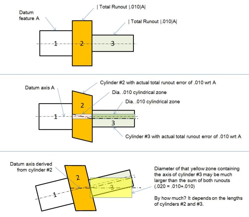
My company are manufacturing a 1800mm shaft for a company. There are 3 diameters on this shaft each with a separate Total Runout specified of 0.076mm

My question is this: If diameter A run out is 0.05 (positive direction on clock) and then diameter B run out is -0.03 (negative direction on clock) then does this mean that the Total runout is 0.080mm ove the two different diameters?
My customers engineer seems to think so but i am not so sure i believe that they are to be assessed individually. I have read the ASME Y14.5 - 2009 standard and it does not advise of any cumulation over different diameters.

I have read thru various posts but none seem to deal with this

Thank you in advance
Martin
 
Replies continue below

Recommended for you

6.7.1.4 Surface Relationship.
Where two surfaces are related to a common datum by runout tolerances, the permissible runout between the two surfaces is equal to the sum of their individual runout tolerances with respect to the datum.

from ASME Y14.5-1994


I cannot find the same statement in 2009 (maybe I wasn't looking hard enough), but I am sure the concept did not change from 1994 to 2009


All I could find was the following section in the section on Runout which seems to indicate that if you want multiple surfaces to be controlled by one FCF tolerance value that you should use multiple leaders.

9.6 SPECIFICATION
Multiple leaders may be used to direct a feature control
frame to two or more surfaces having a common runout
tolerance. Surfaces may be specified individually or in groups
without affecting the runout tolerance. See Fig. 9-6.

I'm not a vegetarian because I dislike meat... I'm a vegetarian because I HATE PLANTS!!
 
Unfortunately the runout chapter of Y14.5 is written in the way that's really vague and sloppy.

"Multiple leaders MAY be used to direct a feature control frame to two or more surfaces having a common runout tolerance (May but definitely not should). Surfaces MAY be specified individually or in groups without affecting the runout tolerance (Affecting which way - making the requirement simultaneous or separate?)"

And like greenimi mentioned, some clear, meaningful paragraph has disappeared mysteriously.

Personally I believe that OP is right and separate runout requirements cannot be made simultaneous.

But this brings in another question. (I know that I am bordering with hijacking the thread) What is the right way to distinguish between (total) runout being applied to multiple features separately or simultaneously?

"For every expert there is an equal and opposite expert"
Arthur C. Clarke Profiles of the future

 
If each diameter has it's own total runout callout then I would measure the total runout on each surface and report them individually. Even if you used one callout with multiple leaders I don't think that implies any mutual dependency.

----------------------------------------

The Help for this program was created in Windows Help format, which depends on a feature that isn't included in this version of Windows.
 
Runout requires it be measured to a reference datum feature/axis. The runout tolerance applied to one feature will have no effect on the runout tolerance applied to another feature when measured from a separate, common datum feature axis. When the two features are measured relative to each other (ie: one of the two features is now also the axis utilized for measurement) the resulting maximum possible deviation will be the sum of the allowable deviation of each feature from the common datum axis.

CheckerHater 30 May 19 13:34 said:
And like greenimi mentioned, some clear, meaningful paragraph has disappeared mysteriously.

Personally I believe that OP is right and separate runout requirements cannot be made simultaneous.

But this brings in another question. (I know that I am bordering with hijacking the thread) What is the right way to distinguish between (total) runout being applied to multiple features separately or simultaneously?
I don't think that paragraph adds much really, thats just an effect of the resulting geometry not in defining the actual tolerance zone(s).

I'm with dgallup, each runout tolerance should be considered individually regardless of how its specified.
 
ASME Y14.5-1994 said:
6.7.1.4 Surface Relationship.
Where two surfaces are related to a common datum by runout tolerances, the permissible runout between the two surfaces is equal to the sum of their individual runout tolerances with respect to the datum.

Maybe they don't have this statement in the standard any more simply because they realized it was not true?
 
tim member said:
Maybe they don't have this statement in the standard any more simply because they realized it was not true?

I do not think that the statement is not true. It is valid. I think has to do with the definition of the runout itself which did not change from 1994 to 2009.
The relationship between two feature defined with runout has a combined effect of the one feature and another feature which is the cumulative effect.

The runout section is the definition of the runout as an individual callout/ specification and not a class/course for the stackup.
 
As greenimi said, it is indeed valid - it just is a result of the geometry and I believe it adds nothing to the actual definition of runout. It is not cumulative when measured to a separate, common datum feature but it is cumulative when measured relative to each other. See my below mock up (I did it rather quickly, hopefully it makes sense).

relative_runout2_myrai1.jpg


Edit: tried to make my image bigger - for some reason they are being shrunk quite a bit.
 
I'm somewhat surprised in the amount of attempts at answers that are being given without seeing the actual callout(s).

Is it possible that there are runout callouts to a common datum for each of these surface. But then there is also one (or more) that also relate the runout of one surface relative to the other surface.

Yet, the sum of the runout to the common axis would only sum to be the same as the runout of one surface referenced to one of the others if the individual runouts were 180° out of phase with each other.

??? thoughts?
 
djhuryat 31 May 19 19:52 said:
Yet, the sum of the runout to the common axis would only sum to be the same as the runout of one surface referenced to one of the others if the individual runouts were 180° out of phase with each other.

I don't need to see the actual callouts, its a result of the geometry.

If you'll notice in my initial response (30 May 19 14:58) I stated "the resulting maximum possible deviation" which I showed in my figure. Less deviation is obviously possible, but we are talking about the worst case.
 
greenimi, chez311,

What do you think about this?
sum_of_runouts_yuq8mw.jpg


I may be missing the point of the statement given in that paragraph 6.7.1.4, but if it means what I think they wanted it to mean (which is basically what you, chez311, showed on your picture), then I still say the statement is not true.

Of course, I hope it's clear from my illustration that because I analyzed possible deviations of the axes of the cylinders and not deviations of the surfaces of the cylinders, I used the idea of a cylindrical tolerance zone centered about the datum axis instead of the idea of a total runout tolerance zone being a space between two coaxial cylinders.
 
The old statement may not be true. If each diameter relative to a third axis has some non-zero value for total runout, and the runout variation for one of those surfaces is due to inclination of a perfect cylindrical surface relative to that third axis, then using that surface to establish an axis could generate a much larger total runout value for the other surface than the simple summation. Especially if the new datum surface is not very long causing considerable wobble.

Edited: I see that in the time I typed the above an example was created.
 
ASME Y14.5M-1994 said:
6.7.1.4 Surface Relationship. Where two surfaces are related to a common datum by runout tolerances, the permissible runout between the two surfaces is equal to the sum of their individual runout tolerances with respect to the datum.

If I had to guess, I'd say this paragraph was probably intended to describe a consequence of the runout tolerances. However, due to the word "permissible", it could conceivably be interpreted as defining an additional requirement to be enforced. Perhaps that's where OP's customer's engineer got the idea.

Regardless of intention, the meaning of "runout between the two surfaces" is undefined. That alone makes the paragraph rather questionable. If we take it to mean "runout of one surface with respect to a datum axis established by the other", then it is either an incorrect description of a consequence (as illustrated by tim_member) or possibly a very restrictive additional requirement. I'm glad it's not present in Y14.5-2009.


MartoL,
[ol 1]
[li]Is drawing interpretation per ASME Y14.5-2009 actually specified?[/li]
[li]Do the three total runout tolerances have identical datum feature references?[/li]
[li]Actual values of runout are never negative. What do you mean by "run out is -0.03 (negative direction on clock)"?[/li]
[/ol]


pylfrm
 
Tim member said:
Of course, I hope it's clear from my illustration that because I analyzed possible deviations of the axes of the cylinders and not deviations of the surfaces of the cylinders, I used the idea of a cylindrical tolerance zone centered about the datum axis instead of the idea of a total runout tolerance zone being a space between two coaxial cylinders.

Why? Isn't it agaist the runout definition being a surface and not an axis control?


Tim,

I stand corrected. I had to think about it for a bit but i agree with your interpretation - with the noted caveat that total runout is of course a surface control. I was caught thinking in 2D instead of 3D and slipped up.
 
Kedu said:
Why? Isn't it agaist the runout definition being a surface and not an axis control?

Although total runout defines a tolerance zone that is two coaxial cylinders which are coaxial with a datum axis, it is quite often, I would say, interpreted in terms of allowance for maximum possible offset between the axis of the toleranced feature and the datum axis. This approach results in a conclusion that the maximum possible axis offset equals to the half of the specified runout tolerance value and so that the axis of the toleranced feature must fall within a cylindrical tolerance zone of a diameter equal to the specified runout tolerance value.

I especially see this approach used in tolerance stack-up analysis and I also decided to use it here. Naturally, the other approach using surface deviations could as well be used to prove that the statement from the standard is not correct.
 
I agree with Tim about the value in sometimes thinking of runout error around the axis, even though the actual tolerance resides around the surface. Runout is a "composite control" that encompasses errors of form, orientation, and location. But it's often easier (as he said, especially for stack calculations) to think of all the error lumped into location error, and proceed from there.

John-Paul Belanger
Certified Sr. GD&T Professional
Geometric Learning Systems
 
Sorry for the delay in reply

In answer to your questions plyfrm

1. No specification on the drawing so in its absence i applied ASME Y14.5-2009
2. Yes
3. for example: the diameter at on end could be +0.03 / -0.01 then at the other -0.03 / +0.01 resulting in 0.06 total between them.

I have attached a section of the drawing to clarify

Martin
 
 https://files.engineering.com/getfile.aspx?folder=18eb8f74-c163-4bbe-b44f-827ff7c6b6d2&file=runout.png
I have a question: How we get positive and negative runout if runout is essentially total indicator movement, not reading. In both cases movement is 0.04 and is not cumulative.

"For every expert there is an equal and opposite expert"
Arthur C. Clarke Profiles of the future

 
Status
Not open for further replies.

Part and Inventory Search

Sponsor