Continue to Site

Eng-Tips is the largest engineering community on the Internet

Intelligent Work Forums for Engineering Professionals

  • Congratulations waross on being selected by the Eng-Tips community for having the most helpful posts in the forums last week. Way to Go!

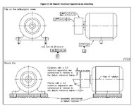
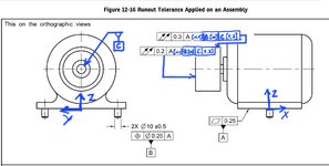
Runout Tolerance Applied on an Assembly 1

greenimi

Mechanical
Nov 30, 2011
2,298
Why runout is used in this figure? (instead of profile)

What would be the difference between using profile (maybe even with dynamic profile modifier) instead of currently shown total runout?
Are there any mathematical difference between shown total runout and profile (again with dynamic profile maybe) ?


QTETIPS - Copy.jpg
 
Replies continue below

Recommended for you

greenimi,
I think that theoretically total runout could be used to control either the major diameter, the minor diameter, and even the pitch diameter of a thread, but not the entire helical surface as a whole feature. The total runout tolerance zone is really only well defined for nominally cylindrical features (or flat ones perpendicular to an axis). Circulat runout can only work for features with circular cross-sections (or flat circular elements), and threads are not round in cross-sections.

Interrupted features such as gears can indeed be controlled by circular or total runout, but that is because you ignore the interruptions and consider only the portions that form a round feature. Threads are not interrupted but the major/minor/pitch diameter could be treated as a cylinder in isolation from the rest of the surface, but only for total runout and not circular runout.
 
Last edited:

Part and Inventory Search

Sponsor