Eng-Tips is the largest engineering community on the Internet

Intelligent Work Forums for Engineering Professionals

  • Congratulations waross on being selected by the Tek-Tips community for having the most helpful posts in the forums last week. Way to Go!

ISO 1101:2012 - Tolerance zone orientation

Status
Not open for further replies.

ortabe

Mechanical
Feb 6, 2009
21
0
0
NL
Hi,

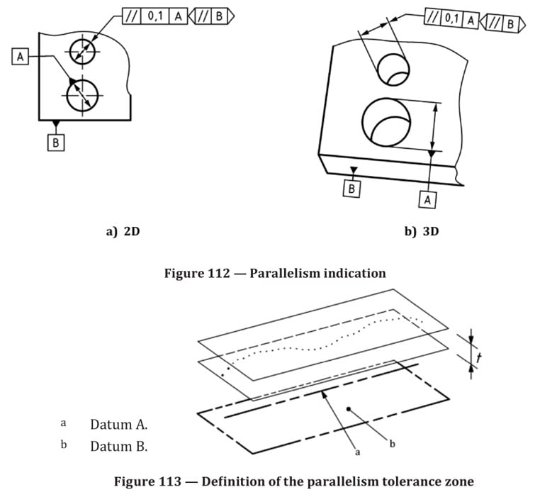
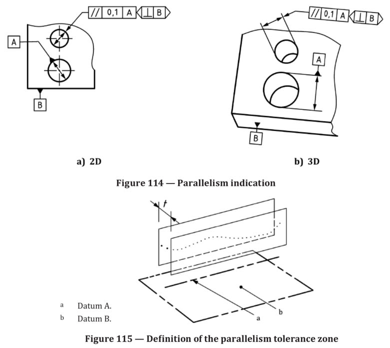
I'm trying to understand how previous editions of ISO 1101 specified the orientation of tolerance zones in the 2D case. Datum A indicates the center of the larger hole and both tolerance zones are parallel to it. Is B now the orientation plane? How does it constrain the tolerance zone further and where is this rule printed in ISO 1101:2012? For one zone it is parallel to B, for the other it's perpendicular so I guess the parallelism symbol only refers to A, not to B.
Edit: Also somewhere it is stated that the leader lines indicate the orientation of the tolerance zone. So there's no need for B here, I think.
tz_cmlk3g.png


Thanks.
 
Replies continue below

Recommended for you

The second one is considered machine readable. Unless the software is really good it would not be able to read the first one correctly.
 
By second, do you mean b) 3D?
Then the first one being a) 2D, I don't mind machine readable.
- Is it correct? (It's straight from the standard)
- How does it constrain the tolerance zone further? Edit: It being datum B.
- Where is this rule printed in ISO 1101:2012?
- Given that leader lines indicate the orientation of the tolerance zone, why is there a need to include B?

Thanks.
 
The orientation of the measurement is controlled by the reference to B. In the first case that relationship is implied by the apparent perpendicularity or parallelism of the tolerance direction.

If B is not used then it isn't clear which direction the two measurements are to made. It might have been relative to the vertical side if B wasn't mentioned.

You should have a copy of 2012. In the 2017 version it's in section 8.
 
Thanks 3DDave, the figure is indeed from section 8 and reading it doesn't clarify how it works for me. My confusion lies in how the relationship is implied. I will expand a bit. I understand that the parallelism symbol relates the tolerance zone orientation to datum A. I think the parallelism symbol does NOT relate the tolerance zone orientation to datum B because otherwise one of the two specifications would be incorrect. Besides, how can we know which zone should be parallel to the horizontal and which zone should be parallel to the vertical?

You say the relationship is implied, what I'm not seeing is how it is implied.

If B was not used the direction would be clear from the leader lines, no?

Thanks.
 
Suppose that the vertical direction was meant to be measured parallel to the side surface and the horizontal direction was supposed to be measured parallel to the bottom surface. By including the datum reference it is clear which surface is the one that orients the measurement. Without it you could not be sure. Since it's not explicit in the callout for the first case it is implied by the orientation of the leaders.
 
Please note the arrow of the leader line gives the direction is a former practice in 2012 version, 2017 version specify the orientation plane indicator on both 2D and 3D print, here is the examples from the ISO 1101 2017 Standard.

1101-2017-1_mywnow.jpg


1101-2017-2_dgc1sg.jpg


Season
 
They really should not use an indicator of width when they mean diameter particularly if the width of the zone is not oriented to match the direction the zone is measured.

They mean well, but I thought they meant datum A was only the vertical width. So simple and they made it worse.
 
Thinking from the perspective of stability of datum system, if only A is used the part will rotate around the datum axis. When B is added, now the part is stabilized. Though one translation degree of freedom is not constrained yet, it does not affect the orientation of the hole.
 
3DDave,

Ah yes, the orientation of the measurement, I see that now.

Do you agree then that in the first case B is not used for the orientation of the tolerance zones wrt the work piece? This is what I was trying to figure out: How does B constrain the tolerance zone? Answer: It doesn't.

Thanks.
 
ortabe,
If B was not used in the first case, the two tolerance zones would still be allowed to freely rotate. Notice that regardless if they were at 0 and 90 degrees to the datum B (nominal condition) or at say 45 and 135 degrees to datum plane B, they would still remain parallel to datum axis A. This in turn would result in an infinite number of solutions, which would have to lead to a conclusion that the drawing specification was vague.

Therefore, a reference to B is needed to constrain that unwanted rotation of the tolerance zones.
 
pmarc,
Indeed there would be an infinite number of solutions (assuming the former practice of the leader lines is somehow insufficient). Then I ask, how does B specify the orientation of the tolerance zones? The one might be at 0 degrees and the other at 90. Or the one might be at 90 degrees and the other at 0. Where in ISO 1101:2012 is the rule that explains how this specification should be interpreted?

I understand the point about measurement. You should place the work piece on a surface plate or such before measurement. I don't understand how B specifies the orientation of the tolerance zones or if B does that at all. It cannot be the parallelism symbol or both tolerance zones would be horizontal and overlap which makes no sense.
 
ortabe said:
how does B specify the orientation of the tolerance zone?

Since B is referenced in tolerance frame, the orientation of the two-planes tolerance zone is at a TED angle to datum B. Generally, the orientation is either perpendicular, parallel, or set by a specified TED angle. The decision of whether it is parallel or perpendicular is according to the leader line direction. The tolerance zone is perpendicular to the leader line. This is indicated in para. 8.2 (page 13):

ISO 1101:2012(E) said:
In 2D view, when the direction of the width of a tolerance zone is at 0° or 90° relative to the datum or relative to the pattern of the theoretically exact dimensions without using an orientation plane, the arrow of the leader line gives this direction (Figures 22, 23 and 24). In other cases, an orientation plane shall be used

Figure 23 which you posted yourself and Figure 24 that shows the interpretation for the tolerance zone of fig. 23 indicate that it is perpendicular to the leader line.
 
Thanks everyone. With all of the mentioned things in mind I'll go over the standard once more. Maybe also some of the answers I'm looking for are in ISO 5459, I'll give that a second read too.
 
Status
Not open for further replies.
Back
Top