Continue to Site

Eng-Tips is the largest engineering community on the Internet

Intelligent Work Forums for Engineering Professionals

  • Congratulations SSS148 on being selected by the Eng-Tips community for having the most helpful posts in the forums last week. Way to Go!

ISO 13920 angle tolerances 1

Status
Not open for further replies.

David HG

Automotive
Jan 29, 2021
10
Hello!

I'm David, a Quality engineer working at Doosan Infracore Norway.

I've questions about ISO 13920 regarding the angular tolerance setting.
I've attached the specific part of the standard below and highlighted some points in question.
13920_Angles_ruxgtt.png


Below are my questions in an image format.
I'll also re-state them here:
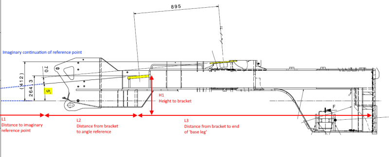
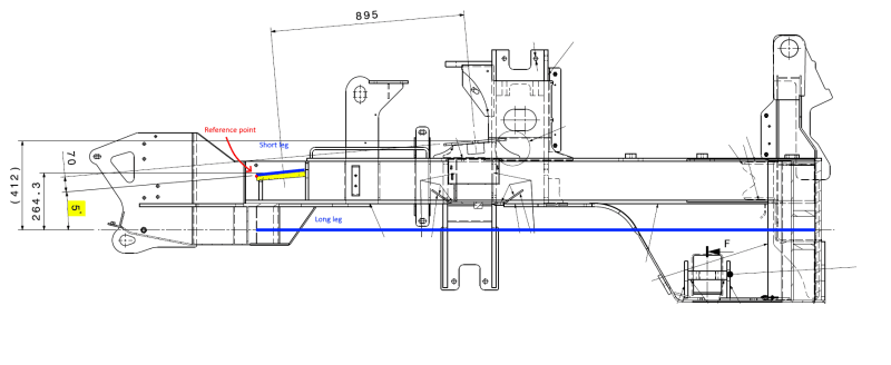
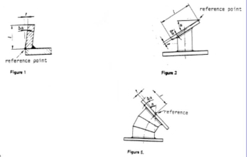
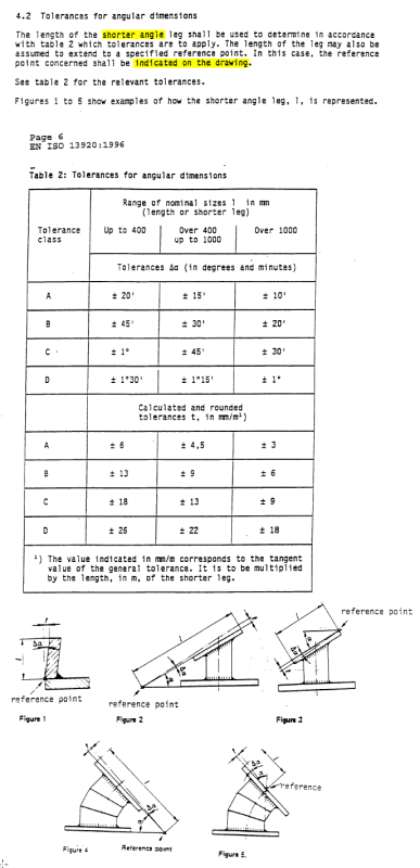
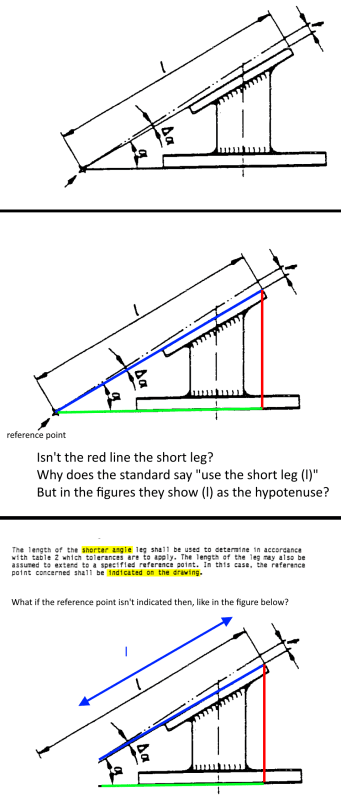
- The standard emphasizes the short leg shall be used as l to determine tolerances from Table 2.
However inside the Table 2 it says l = length or shorter leg.
And inside all figures it is shown that l = hypotenuse only. (Going against the first statement)
What is correct?
- It also states the reference point shall be indicated on the drawing. What length l values shall be used if it isn't indicated?
13920_Questions_qrb1bg.png
 
Replies continue below

Recommended for you

"I" is the shorter leg among the two legs forming the angle.
If the reference point is not indicated then the same rule applies, but the shorter leg's length is shorter and it is only the length of the part feature that forms this leg.
Your green line should extend till the end of the base of the part. Then the blue line is the shorter among the blue and the green.

 
@Burunduk

1. You write "I", do you mean I, or lower case l. In the standard I only see reference to lower case l which seems to be the hypotenuse in the examples.

2. So in the figure in my previous post I shall extend the green line to the end of the base leg?

3. So I can better understand point 2., lets ground this in the actual case I'm wondering about.
Example_whjclq.png


I want to find that angle tolerance to use for the 5° angle to the first bracket (just left to the top of H1 arrow).
3.a What value should I use as "l" in this case (to find a tolerance in ISO13920 Table 2)?
Is it the distance from the 5° angle to the bracket (left to the top of H1 dimension) the shorter leg in this case?
3.b Should I draw the base leg all the way from L2 + L3?
 
David,
1. I mean l. Sorry for the confusion.
2. Yes.
3. 5° in your drawing is shown without a reference point so you need to compare the lengths of the features between which the dimension is given. What is the horizontal reference for the bracket's 5° orientation? There is some theoretical line, can't tell from this view what it represents.
 
Hi Burunduk,

3.
5° angle feature:
Bottom leg: Horizontal reference point extending to the RHS end of distance L3. This is the centre of a round machined surface.

Do you mean the base leg should be from the 5° to the horizontal start of height H1?
 
David,
The axis of a cylindrical feature is not a good reference from which to measure the angle of a planar feature so I guess you are not in an easy situation dealing with this drawing as a Quality engineer. Also, you say that the horizontal reference extends to the end of L3 but it doesn't seem to be unequivocal from the drawing. Looks like that cylindrical feature is interrupted and it could be interpreted that only the left-hand side provides the reference axis. I would interpret it this way because the axis centerline isn't shown continuous, rather there are two separate centerlines and the 5° dimension is given from one of them. Either way, it seems by the proportions that the bracket is the shorter leg regardless of how the horizontal reference is interpreted so I guess that at least regarding deciding which leg is "l" and what its length is, there shouldn't be a problem in this specific case.
 
Hi Burunduk,

Sorry for the confusion, but the centerline is continuous, I've edited out features to try sensor the drawing, and the middle of the centerline was deleted in the picture editing software.

"[...]it seems by the proportions that the bracket is the shorter leg"
So do you mean "l" = the distance from the 5° text to the RHS end of the bracket? Or simply the width of the yellow marked bracket?
 
Hi David,
I mean that the length of the shorter leg is the length of the yellow bracket only. That's because there is no reference point indicated on the drawing. The location of the 5° text doesn't matter.
 
Burunduk,

Ah I see.
Thank you for your help!

Can you confirm the visual representation of the legs looks like this then: (Short leg = Length of bracket. Long leg must still be aimed at the feature the angle is taken from (cylinder at the RHS end), and 5° text placement doesn't matter you said, so it must start from the bracket's start?. Reference point = LHS end of bracket)
Short_leg_ebi41a.png


Same drawing without markings (for reference):
No_markings_zkdggz.png
 
Hi David,
I hope there was no misunderstanding from my side.
I probably should have asked you this question earlier:
What is longer, the horizontal cylinder from which the axis is derived, or the yellow bracket?
 
Hi Burunduk,

See picture below. The centerline is based on plane A and B. The horizontal cylindrical length is 10mm.
The yellow bracket is 230mm.

rear_yzpsfx.png


If I understand your implication correctly, do you mean the cylindrical surface is actually the short leg?
How could I visually represent this, with a long leg, short leg, and reference point? I sure cannot just shift the reference lines around at will, they must point towards the actually features referred to, correct? (Like in the picture with blue lines in my previous post).
 
David,
It appears that there was a misunderstanding from my side. I previously got the impression that the horizontal feature from which the angle dimension was given was much longer and extended throughout most of the part.

Now it appears that:

[ul]
[li]The length of the horizontal cylindrical feature is 10mm.[/li]
[/ul]

[ul]
[li]The length of the bracket is 230mm.[/li]
[/ul]

[ul]
[li]5 degrees angle dimension is specified between the horizontal cylindrical feature's axis and the bracket, without a reference point[/li]

This means that the length of the shorter leg is 10mm, and this is the value with which to approach the table from the standard to determine the tolerance for the angle.

To clarify this a bit: If you consider the image you posted from the standard (the one where you added the green and blue lines) if it wasn't for the reference point, the length of the green line should have been the length of the flat bottom face, and the length of the blue line should have been the length of the top slanted face. If instead of a flat surface the axis of a cylinder is used as one of the angle legs, then by extension of the principle shown in the standard the length of the cylindrical feature is what sets the length of the leg (again, as long as there is no reference point indicated. Otherwise both legs are extended until the reference point). You mentioned visual representation. I am not sure what exactly you are concerned about. I can only say that to represent it clearly, the axis centerline should be shown much shorter. Extension lines from the 5° dimension connect to the axis and the bracket. Bear in mind that extension lines' length is not relevant to the determination of the length of the angle legs.
[/ul]
 
Hi Burunduk,

"Bear in mind that extension lines' length is not relevant to the determination of the length of the angle legs."
I guess this is where my confusion came from. Looking at the standard the length was always extended to a reference point. Having the reference point removed I assumed this simply moved to the end of the extension lines to the 5° text.
So in conclusion:
Reference point: Legs = End of feature, extended to the reference point.
No reference point: Legs = Only the physical lengthwise features make up the leg lengths.

Thanks!
 
David said:
Reference point: Legs = End of feature, extended to the reference point.
No reference point: Legs = Only the physical lengthwise features make up the leg lengths.

Correct.
Just to be super-clear:
In the typical case where there is a reference point, the length of each leg is the length of the physical feature plus the length of the distance from the end of the feature to the reference point in the feature's length direction, as shown by the green and blue marked lengths here:
20210205_101922_ui9np7.png


But not like this:
20210205_102856_xp3wd9.png


Without a reference point, the determination of the leg lengths is done according to the physical lengths, like this:
20210205_105143_vi0iw0.png


However: with a reference point, there can also be some tricky situations where the physical length of one of the features is not considered. Then the length of one of the legs is from the reference point all the way until being "cut" by a theoretical extension from the corner where the other feature ends, as in these figures:
20210205_103801_wvncdk.jpg
 
Status
Not open for further replies.

Part and Inventory Search

Sponsor