Continue to Site

Eng-Tips is the largest engineering community on the Internet

Intelligent Work Forums for Engineering Professionals

  • Congratulations KootK on being selected by the Eng-Tips community for having the most helpful posts in the forums last week. Way to Go!

ISO 2768-mK and gage size 3

Status
Not open for further replies.

Andera

Mechanical
Jan 21, 2019
58

If an outside cylindrical surface (defined on a drawing calling out ISO 2768-mK and DIN 7167) has a diameter of Ø12mm (+0.2 / -0.1) what would the correct “GO” gage size dimension (inside diameter of the gage) to verify this OD requirement?

I would appreciate someone with ISO knowledge to help me getting the right gage size.

I looked up online for DIN 7167 and found some recommendation such as: ”The issuing body recommends using DIN EN ISO 14405-1:2011-04 .”

I did not see DIN 7167 having the envelope requirement by default so, I am little bit confused about the appropriate gage dimension.

Any help will be greatly appreciated.

Thank you
 
Replies continue below

Recommended for you

Just a guess, as I am not an ISO type of guy...

If circular runout per ISO 2768-mK is by default limited to 0.2mm then I would tink that the gage size would be 12 + 0.2 ( max size) + 0.2 (runout)= 12.4.

Am I correct?

Would be nice if someone with more ISO experience would confirm.

I know some members of this forum have good grasp on ISO stuff.

 
ISO 2768-2 states:
ISO 2768-2 said:
5.1.3 Cylindricity
General tolerances on cylindricity are not specified.
NOTE 1 The cylindricity deviation comprises three
components: circularity deviation, straightness deviation and
parallelism deviation of opposite generator lines. Each of these
components is controlled by its individually indicated or its
general tolerance.
NOTE 2 If, for functional reasons, the cylindricity deviation has
to be smaller than the combined effect (see clause B.3) of the
general tolerances on circularity, straightness and parallelism,
an individual cylindricity tolerance in accordance with ISO 1101
should be indicated for the feature concerned.
Sometimes, e.g. in the case of a fit, the indication of the envelope
requirement is appropriate.

The "m" defines the tolerance of the linear (point-to-point) dimensions, the "K" the straightness and circularity tolerances. You would need to combine all those to get the gauge dimensions.

ISO 2768-2 said:
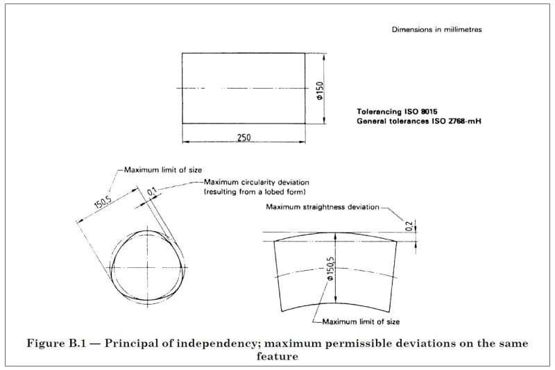
B.1 General geometrical tolerances
(see clause 5)
According to the principle of independency
(see ISO 8015), general geometrical tolerances
apply independently of the actual local size of the
workpiece features. Accordingly, the general
geometrical tolerances may be used even if the
features are everywhere at their maximum material
size (see Figure B.1).
ISO_2768-2-B.1_u53duw.jpg


However, if as you indicate, the 12 mm diameter has an individual tolerance assigned (+0.2/-0.1) then the first part of ISO 2768 (the "m") does not cover this dimension.
But without additional geometric tolerances the "K" would still define the maximum allowable circularity and straightness deviations. ISO 2768-K would limit the total permissible circularity deviation to 0.2 mm even if the permissible linear diameter deviation is greater. This is regardless of diameter size.
In your case - linear diameter tolerance is larger (+0.2/-0.1 = 0.3) than the allowable circularity deviation (0.2) - the circularity deviation of every ring along that cylinder is not allowed to exceed 0.2, regardless of the diameter size. So the diameter of each ring can be anywhere between 11.9 mm and 12.2 mm but its circularity has to be within a 0.2 mm boundary.

ISO 2768-2 said:
The permissible deviation of the diameter is
indicated directly on the drawing; the general
tolerance on circularity is equal to the numerical
value of the diameter tolerance.
EXAMPLE 2 (see Figure B.2)
The general tolerances in accordance with the
indication ISO 2768-mK apply. The permissible
deviations for the diameter of 25 mm are ± 0,2 mm.
These deviations lead to the numerical value
of 0,4 mm which is greater than the value of 0,2 mm
given in Table 4; the value of 0,2 mm, therefore,
applies for the circularity tolerance.
ISO_2768-2-B.2_bbuuwp.jpg


The resulting cylinder would still be allowed to have local diameters between 11.9 mm and 12.2 mm.

The straightness allowance would however depend on the length of that cylinder.

If the diameter dimension has, additionally to the size tolerance, an encircled "E" behind it then you treat it like an envelope (just as with ASME 14.5)
If you want to be able to gauge this cylinder it would be advisable to invoke the Envelope principle for this feature.
 
Andera said:
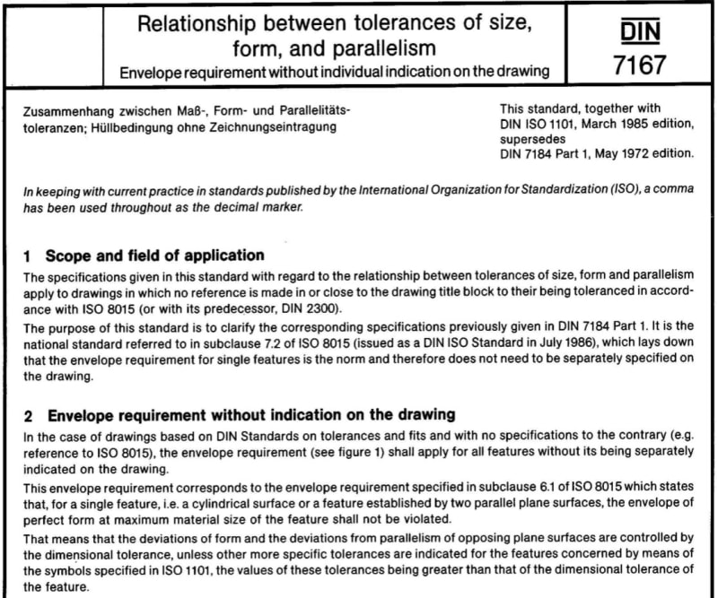
I did not see DIN 7167 having the envelope requirement by default so

2019-04-28_114929_etuekc.jpg


Attached above is DIN 7167 regarding the evelope requirement, but it was withdrawn as I know, and in case the envelpoe requirement is required, the drawing callout may change from ISO 2768-mK to ISO 2768-mK-E, where E means the envelpoe requirement shall be added.

Season
 
Thank you very much for the pertinent advice.
Unfortunately, the envelope requirement is not in effect, as far as I understood. I do not have the authority to change the drawing to enforce E envelope.
A GO gage has been requested to be designed and built to check the maximum material requirement of the cylindrical surface and I was confused what would be the correct size.
Looks like a 12.2mm is a convervative dimension to be used. It is like in statistics: type one error, manufacturing risk- if I remember that class correctly from my college classes.
 
I would say your maximum envelope should be 12.3 mm (12.2 mm + the 0.1 mm for the maximum allowed straightness deviation) while your minimum envelope (perfectly straight, perfectly round) would be 11.9 mm
 
Also, always keep this one in mind:
ISO 2768-2 said:
7 Rejection
Unless otherwise stated, workpieces exceeding the
general geometrical tolerance shall not lead to
automatic rejection provided that the ability of the
workplace to function is not impaired
(see clause A.4).
 
Th.Ro,
Thank you very much. I appreciate your quick reply.

May I ask what is the relevance of the cylinder lengths? Otherwise stated, why cylinder's length is important for the correct size of the GO gage?
Not sure I fully understand ISO system. Thanks again.
 
Andera,

Do you have control over (or knowledge of) the manufacturing process for this surface? If so, what is it?

Gages will generally allow rejection of some good parts, acceptance of some bad parts, or both. How do you want that handle that for this application?


pylfrm
 
Pylfrm,

pylfrm said:
Do you have control over (or knowledge of) the manufacturing process for this surface?

No, I do not. I am just designing gages per customer provided drawings and requirements.

pylfrm said:
Gages will generally allow rejection of some good parts, acceptance of some bad parts, or both. How do you want that handle that for this application?

I am talking about the nominal GO gage dimension and not about its applicable tolerance. The gage tolerance I will determine per our gage policies (absolute, pessimistic, optimistic, tolerant-tolerancing) and agreement with the customer.
 
Andera said:
May I ask what is the relevance of the cylinder lengths? Otherwise stated, why cylinder's length is important for the correct size of the GO gage?

The length gives you the permissible straightness deviation. This has to be considered as well for a gauge.

ISO_2768-2-T.1_ci0xhu.jpg
 
Andera,

Just out of curiosity, what is the part material? Do you at have a guess at the manufacturing process? This information is generally used to predict what sort of deviations are likely (or unlikely) to be present in actual produced parts, allowing the inspection process and gages to be designed accordingly.

I realize you are talking about the nominal gage dimension. Imagine you have an external cylindrical surface with a diameter tolerance of 8 +/- 0.5 and a straightness tolerance of 1.0 @ MMC, and you want a GO ring gage to check compliance with the upper limit of the diameter tolerance. If you want to reject all bad parts, the straightness tolerance doesn't matter and the ring gage hole diameter should be 8.5 (with a minus tolerance). If you want to accept all good parts, the straightness tolerance must be allowed for and the ring gage hole diameter should be 9.5 (with a plus tolerance).


pylfrm
 
pylfrm said:
I realize you are talking about the nominal gage dimension. Imagine you have an external cylindrical surface with a diameter tolerance of 8 +/- 0.5 and a straightness tolerance of 1.0 @ MMC, and you want a GO ring gage to check compliance with the upper limit of the diameter tolerance. If you want to reject all bad parts, the straightness tolerance doesn't matter and the ring gage hole diameter should be 8.5 (with a minus tolerance). If you want to accept all good parts, the straightness tolerance must be allowed for and the ring gage hole diameter should be 9.5 (with a plus tolerance).

Sorry to be nosy, but could you, please explain a bit more?

Why straightness tolerance does not matter in ISO? (I am sure matter in ASME as a derived median line straightness, but that is beside of the point)

I am sure I’m missing something due to my lack of ISO education, but pylfrm’s example (and also OP original example) looks pretty basic.

Using Ø8.5 –as indicated —for the nominal ring gage hole diameter – with a minus tolerance — you are going to enforce the envelope concept, don’t you? Since it is an ISO standard with no E, envelope requirement implied, how the gage tolerancing policies, as specified above by the OP, will be affected?

Thank you again for your valuable input

 
pylfrm said:
Just out of curiosity, what is the part material? Do you at have a guess at the manufacturing process?

There are two materials assigned to this part: Nylon 6 resign / polyoxymethylene and brass rods per SAE CA 360 or SAE 72 (half hard temper).

I don't even want to guess the manufacturing method or subsequent processes nor the customer application. Maybe HVAC or around those lines.
 
greenimi,

I don't know what various standards might be involved in the requirements of OP's feature. Whatever they are, I am probably not very familiar with them. That being said, I think the general concept of my (admittedly ASME-themed) example should be pretty universal.

Imagine an actual part that is a perfect cylinder of diameter 8.501. This part meets the straightness tolerance, but not the diameter tolerance. If we want the GO ring gage to reject it, the hole diameter must be smaller than 8.501. This would enforce the envelope principle regardless of whether it actually applies to the tolerance in question.

Now imagine an actual part where all the local sizes are 8.499 and the circumscribed cylinder diameter is 9.499. This part meets both the straightness tolerance and the diameter tolerance. If we want the GO ring gage to accept it, the hole diameter must be larger than 9.499.


pylfrm
 
Sure this is an interesting stuff:

Quote said:
Quote (ISO 2768-2)

The permissible deviation of the diameter is
indicated directly on the drawing; the general
tolerance on circularity is equal to the numerical
value of the diameter tolerance.
EXAMPLE 2 (see Figure B.2)
The general tolerances in accordance with the
indication ISO 2768-mK apply. The permissible
deviations for the diameter of 25 mm are ± 0,2 mm.
These deviations lead to the numerical value
of 0,4 mm which is greater than the value of 0,2 mm
given in Table 4; the value of 0,2 mm, therefore,
applies for the circularity tolerance.


My question for the ISO users is then why the GO-gage dimension (as requested by the OP) is not the MMS (12.2mm) + 0.2 (default circularity per shown standard ISO 2768-mK) = 12.4mm?

Th. Ro said:
Th.Ro. (Mechanical) 29 Apr 19 23:11

I would say your maximum envelope should be 12.3 mm (12.2 mm + the 0.1 mm for the maximum allowed straightness deviation) while your minimum envelope (perfectly straight, perfectly round) would be 11.9 mm

Why straightness is taken in consideration and not circularity to get the GO-gage size dimension?


greenimi,

The appropriate size for a GO gage depends on what the gage is supposed to do. I asked OP this, but never got an answer.

Now you're asking about gage size, so you should explain what you want your imaginary gage to do.


pylfrm
 
Pylfrm,
I started with the gage group for an HVAC company and one of the requests I got was to design a GO gage to check the specified size cylinder. All my previous designs were based on an ASME definition drawings so much easier to find out the correct GO size gage.

This time the component drawing is based on the above standards (ISO product definition) hence my questions above.

What I do know is that a Go gage suppose to check if it is no material where not suppose to be material therefore the GO gage will go.

The requester did not specify that the GO gage check only the size or only the circularity or only the straightness, but rather the combination on all of those above. At least that is my current understanding of the gage design request. The request mimic exactly a previous request done by a former gage designer (completed within ASME boundary product definition)


Status
Not open for further replies.

Part and Inventory Search

Sponsor