Eng-Tips is the largest engineering community on the Internet

Intelligent Work Forums for Engineering Professionals

  • Congratulations waross on being selected by the Tek-Tips community for having the most helpful posts in the forums last week. Way to Go!

ISO CSYS in Drafting 2

Status
Not open for further replies.

Kenja824

Automotive
Nov 5, 2014
949
0
0
US
When doing work for GM, we have the luxury of using their toolkits with buttons that dont seem available in NX.
We are now doing non-GM work and have to use a different session of NX that is not connected to their toolkits, as they do not want us using their tools to do others work.

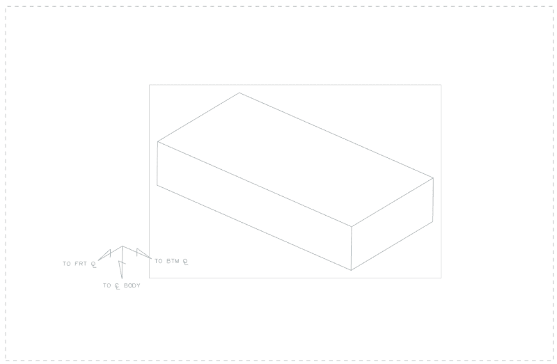
One program GM has that comes in handy is in Drafting, it creates a Trihedron symbol you can place on the sheet and it will come in at the same angles as the XYZ for the ISO view we select.

Looking into it, I find it is not a symbol but it just draws it to the same angles as the view you select. Is there a manual way of creating at least the three lines in the right directions easy? When I just try to draw a line, it will not let me select an edge or anything in the view to give it the direction. So currently I am only able to eye it and draw the line at an angle close. With some people's perception, this can lead to some ugly drawings. lol

I found another thread where someone else was looking for something like this and the advice was to save a CSYS in the view. If that is the only option that is one thing, but when I printed it like that, it doesnt show the arrows, so I would like to find something that looks a little better when done.

image_pkre0y.png
 
Replies continue below

Recommended for you

Once you have the CSYS of the view saved, can't you create 3 lines with arrowheads to show the vectors.
There is an Arrowhead GRIP program in the GRIP library that will draw an arrowhead at the end of any selected line.


"Wildfires are dangerous, hard to control, and economically catastrophic."

Ben Loosli
 
If the trihedron is always connected to one individual view, you can also draw it using the "Sketch in View"
There you should be able to align with edges.

Ronald van den Broek
Senior Application Engineer
Winterthur Gas & Diesel Ltd
NX9 / TC10.1.2

Building new PLM environment from Scratch using NX12 / TC11
 
I had a brilliant idea of trying to import a parasolid Trihedron into the expanded view and moving it to the correct position. Didnt let me.

I tried importing a part file with a trihedron made out of lines into expanded view. Came in 2D.

I tried looking for an arrowhead grip program/Library and cant find anything like that.

I dont like saving the CSYS in the expanded view because it gives us an XYZ and in automotive we use FOL BOL & ℄Body, and the arrows disappear when you print it.

So far drawing it fresh seems the only way, which really surprises me as the CSYS is such a major component to working in NX. I would expect it to have a way to place a CSYS on the drawing sheet that would associate to a view you choose.
 
Actually I cant since it was only a temporary file I made just to create the example.
I created a block in modeling
placed a view in drafting
Then added the trihedron from the GM program.

The trihedron is all just drawn lines from their program. Not a symbol or anything.

I could recreate it and upload it if that would help..?
 
I just recreated one similar to it.

The trihedron is all lines and three notes.

The program must draw it according to the view I guess. After starting it, it asks you to select a view for orientation and then to pick a position on the screen to place it.
You then have the ability to click different options like scale, reposition etc...

Just out of curiosity alone I would be interested on knowing how it knows the CSYS orientation from clicking the view. Sounds pretty in depth to me. lol
 
 https://files.engineering.com/getfile.aspx?folder=88eace44-1545-4e60-9461-4e741a37c222&file=model1.prt
The orientation of the csys is taken from the view indeed.
If you ask the information on the view, you will find the "Rotation Matrix" close to the bottom of the information.
Most probably they are using this information.

Ronald van den Broek
Senior Application Engineer
Winterthur Gas & Diesel Ltd
NX9 / TC10.1.2

Building new PLM environment from Scratch using NX12 / TC11
 
Hi Cowski,

Quickly tested your tool.
After I have been prompted to select a view, I am asked to pick a point. The question is however not showing in the point picker.
(would be nice to see it in the topbar of the point picker)
pointpick_tcdthu.png


Only in the command bar at the bottom.

CommandBar_a4sxbb.png


After picking the point it places the triad just fine.

Nicely done [thumbsup]

Ronald van den Broek
Senior Application Engineer
Winterthur Gas & Diesel Ltd
NX9 / TC10.1.2

Building new PLM environment from Scratch using NX12 / TC11
 
This works almost perfect Cowski.

One minor problem for me. The size of the ISO CSYS it draws changes according to the scale of the view. So for a view of a large assembly, the scale makes it quite small.


I have spent this morning seeing if I can figure out how to keep the scale to always show up as if it was a 1:1 scaled view. Not doing so well. lol My thought was to create a function that would simply take the view that is already selected and find its scale and return a Double (I guess you would call it) using an equation 1 / View Scale. Then the lengths of all the lines would be multiplied by that function result. (If that makes sense) Which this idea is probably way off for what needs to be done anyway. lol

Then as I was failing at that, I realized this would not change the scale of the text in the CSYS "X", "Y" & "Z".

I think I have decided I need to start going through all of my Journals and find particular bits of code and make notes on how they work, so when I need to do something similar I will refer to it and understand how to put them together. I just never retain anything I am learning in this. lol
 
@NutAce,
I agree, I would like to see the prompt text in the dialog itself. However, this isn't how the command works and I have no control over the text placement. Hopefully they will update the NXOpen dialogs in a future version of NX, but I suspect the "solution" would be to use a blockstyler dialog (which I don't have a license for at the moment).

@Kenja824,
Updated code here. It isn't heavily tested, so please try it out and report back.

www.nxjournaling.com
 
Status
Not open for further replies.
Back
Top