Eng-Tips is the largest engineering community on the Internet

Intelligent Work Forums for Engineering Professionals

ISO GPS - Position & Profile of a Surface

Status
Not open for further replies.

Mech1595

Mechanical
Oct 16, 2023
29
0
1
US
Hi Everyone,

I've got another ISO GPS question for you from a customer-supplied print:

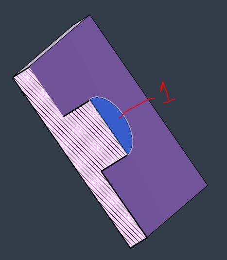
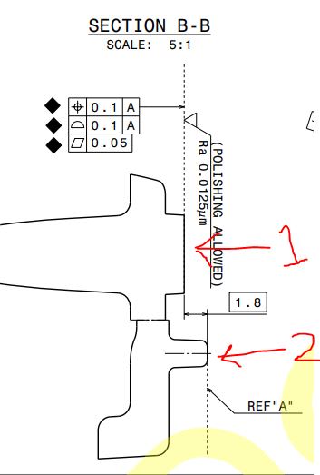
In the image below, aren't the [Position|0.1|A] & [Profile|0.1|A] controlling the exact same thing? I'm struggling to get a response from the customer on this one, was hoping you could provide some insight. To me, both controls create a 0.1mm tolerance zone nominally located [1.8] from Datum A. Am I interpreting this incorrectly?

For context, their intent is to control Surface 1 with these callouts (this is a cylindrical feature ~6mm in diameter). Datum A is defined as the end of the standoffs (Surface 2) shown in another drawing view.


ISO_Position_Profile_nsfop0.jpg
 
Replies continue below

Recommended for you

It's a bit more bizarre that the surface roughness that large is concerning enough to parenthetically allow polishing.

Maybe they don't know what they want and are just throwing as much at the problem as possible and hoping it comes out OK.

In any case, unless you think there is a conflict in the requirements, just quote/bill them for the extra inspection step. If they want a lower price, mention that these appear to be redundant and show how much that would save them.

Do they have an incoming inspection group? That might be a place to get a faster response.
 
Surface Profile and Position act the same on a planar surface in ISO GPS, but you are saying it's a cylindrical surface?
I'd say snippet shows too little to understand the problem and form an unequivocal conclusion.
 
3DDave:

3DDave said:
It's a bit more bizarre that the surface roughness that large is concerning enough to parenthetically allow polishing.

This is an optical component, so they like to specify some surfaces as "No polish allowed" (I.e. milling finish only per optical constraints) to avoid further manual influence on the photometric performance. This is typically indicated on the more complex geometry (think reflex optics, light pipe teeth, etc.). This particular surface (Surface 1) is the point of LED input.


3DDave said:
Maybe they don't know what they want and are just throwing as much at the problem as possible and hoping it comes out OK.

Nailed it. This customer is notorious for indicating every single dimension as "critical", which triggers capability studies and in-process inspection requirements. But of course, they never want to pay for the amount of labor and fixturing required to meet all of those requirements.....it's always a fight during quoting.


3DDave said:
Do they have an incoming inspection group? That might be a place to get a faster response.

Oddly enough, this customer does not perform any incoming inspection, outside of visual/appearance during assembly. It's always something I've found odd, especially with how stringent their quality department is. It's a question I've asked multiple times to their SQE's.


Burunduk:

Burunduk said:
Surface Profile and Position act the same on a planar surface in ISO GPS, but you are saying it's a cylindrical surface?

Sorry, I did a poor job of explaining that. Surface 1 is the planar surface at the end of a cylindrical feature. Example Below.

Cyl_Ex_nhy9yy.jpg
 
Mech1595 said:
aren't the [Position|0.1|A] & [Profile|0.1|A] controlling the exact same thing?

The use of the position symbol is allowed according to ISO 1101, but only for planar features.
Both position and profile callout indicate the location of planar feature.

2024-08-09_081557_jtxpnr.jpg
 
Ok, so it's the flat end of a boss. That also explains why there is a flatness specification.

BTW, Ra of 0.0125 micrometers requires the surface to be extremely smooth. So polishing is totally relevant.
 
Thanks for the quick feedback everyone.


Burunduk said:
BTW, Ra of 0.0125 micrometers requires the surface to be extremely smooth. So polishing is totally relevant.

Yep, this is essentially the lower bound of a SPI A1 finish. Very common for these optical components.
 
Ah - being sideways I missed the leading zeros. Oddly, don't metric system users pride themselves on using the appropriate modifiers so there are few needs to use a value that is less than one? 12.5 nm anyone? nm is pretty common in optics; surprised they don't use it here, but conventions get established all the time.
 
The use of the position symbol is allowed according to ISO 1101, but only for planar features.
A quick correction, just for the record: ISO allows position not only for planar features, but also for cylindrical features of size (holes, pins, etc.).
 
Garland23 said:
ISO allows position not only for planar features, but also for cylindrical features of size (holes, pins, etc.).

What you said is absolutely right.
We are talking about the legitimacy of the location tolerance on an integral surfaces, whether it meets the requirements of the ISO standards. On this particular case, position is allowed to use on the planar features only.


Status
Not open for further replies.
Back
Top