Continue to Site

Eng-Tips is the largest engineering community on the Internet

Intelligent Work Forums for Engineering Professionals

  • Congratulations KootK on being selected by the Eng-Tips community for having the most helpful posts in the forums last week. Way to Go!

Isochronous load sharing Vs Droop control with PMS

NickParker

Electrical
Sep 1, 2017
412
What is the actual difference between "isochronous load sharing" and "all the machines operated in Droop mode with PMS control" as both control methods seems similar; both controlling the frequency of all the generators in parallel operation.
 
Replies continue below

Recommended for you

My experience is with PID controllers. Load control panels may operate differently.
PID, Proportional, Integral, Derivative.
Droop is a type of proportional control.
In older plants, all machines responded to load changes in Droop.
One and only one set would be the swing set that controlled the frequency.
Isochronous or Integral control responds firt in droop. The governor then recognizes the error and corrects the error back to the set frequency.
The other parallel sets follow the swing set.
I was for a time the system engineer of a very small utility. 2.2 MW installed, but with loads often under 600 kW and at times under 350 kW.
The system ran in droop for years and the customers never noticed.
If you had a very old electric clock with a synchronous motor, it would not keep accurate time, but those clocks are all long gone.
Even with isochronous control, the frequency is not perfectly stable but varies with load variations and then corrects.
But wait for CR to post in.
 
Thanks much for the vote of confidence, Bill, although I fear it may be misplaced . . .

As to Nick's question, I'll have to read up on that, as I never operated that type of smaller isolated system.

What I did do was Google "droop control with PMS" to find out what PMS meant; there was a search result for a discussion thread at a control.com forum that I found highly informative.

I do find the term "isochronous load sharing" both contradictory and confusing; Bill's system with an isochronous swing set and all other units in droop is much closer to my experience, with a Balancing Authority somewhere in the picture directing the synching, loading, loading adjustments, unloading and shutting down of generation as dictated by prevailing conditions, be they economic, political, resource driven [I.e., surplus or lack of water for hydraulic generation], technical, breakdown, etc., etc.
 
PMS:
Power Management System
Consider a distributed generation system.
One set is the swing set and is using the Integral function of the governor. (Not all governors will have this feature, most are simple Proportional (Droop) control)
As the system load increases, the swing set will pick up the added load.
When the load on the swing set reaches a predetermined limit, the PMS will add generation to the system.
This may be directing a hydro unit to go from 10% output to 90% output.
The PMS will continue to add generating capacity until the load on the swing set drops into a predetermined range.
When the load on the system is decreasing, the swing set load will be dropping and the PMS will remove capacity until the swing set loading rises into a predetermined range.
This is automatic in most utilities as far as I know.
At one time it was manual.
Operators in a load dispatch center would monitor the load on the swing set and would direct the operators at individual generating sites to add or remove capacity.
This was originally done over a POTS. (Plain Old Telephone System)
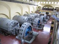
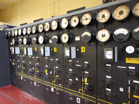
Years ago I was visiting a very old hydro station. It was completely manual.
While I was there, the telephone rang. It was the load control center instructing the operator to take one set from 10% to 90%.
The operator turned a switch that activated a solenoid valve and directed water to a small pelton wheel driving a hydraulic pump.
He then moved over to another control that activated a solenoid valve on the hydraulic system.
Down on the floor, a very tall hydraulic cylinder started to extend. It was connected to a bell crank that controlled the water gates.
While doing this he was watching his power factor meter.
As the set was loading up, the PF was dropping.
He moved over to another control that increased the excitation and raised to power factor.
When I said manual, I meant completely manual. these sets did not even have Automatic Voltage Regulators.
The operator adjusted the excitation several time before the set was up to 90% output.
Note: At 100% load, the set may not have reserve to help support block loading.
MACHINE FLOOR.jpg2016-06-13.jpg

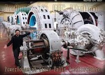
images.jpgRELATIVE SIZE.jpg
I believe that the commutator machine is an exciter. The output would be controlled by rheostat control of the exciter field.
 
I digress. Please forgive me.

https://www.bchydro.com/community/r...ct&utm_medium=redirect&utm_content=stavefalls

FROM WIKI
Stave Falls Dam is a dual-dam power complex on the Stave River in Stave Falls, British Columbia, Canada. The dam was completed in 1912 for the primary purpose of hydroelectric power production. To increase the capacity of Stave Lake,........ The original Stave Falls powerhouse was once British Columbia's largest hydroelectric power source, and is a National Historic Site of Canada.

https://en.wikipedia.org/wiki/Stave_Falls_Dam_and_Powerhouse
 
To my understanding, a Power Management System could be applied in multitudinous ways; however the method chosen for this would have to be based on the circumstances encountered in each case, and these are finitely huge.

By way of example: in an isolated plant with numerous, meaning a dozen or so, Diesel engine driven generators of various ratings, a digital PMS could be loaded with the operating parameters of each generating set. When given control of the system, it would start units, load them to minimum continuous, then ramp their outputs up or down as it "chases the load", shutting units down when no longer required, etc., etc.

The algorithm generally used would be to provide the next kilowatt of needed power based on whichever unit can produce it at the lowest incremental cost. Note that this is based on cost, NOT on efficiency. Note: determining incremental cost used to be an immensely iterative process that taxed available computers to their limits; for some time now, though, using quadrantal calculus, the calculations could be performed as frequently as every two seconds without difficulty - or so I was once told, and that was back in the 1990s.

Each unit would have its own self-contained governor, but the PMS would perform the speeder gear adjustments as required to achieve optimal incremental cost operation, as well as selection of which unit to operate in isochronous mode while leaving the rest in droop mode. By this means the combination of generators would provide quite precise frequency control, with the PMS tweaking the speeder gear settings of all droop units on a follow-up basis. By this means, even the power output of the isochronous one would eventually be brought to its optimal incremental cost.

All of this would be performed around the clock, without human intervention.

Voltage and reactive power control for the site would be similarly arranged, and take place in concert with the PMS.

Perhaps this could be applied to a small consolidated system having a few different generation sites of different types, but as you can imagine the programing of such a PMS would likely become an ongoing task.

Now try adding commercial contracts into the mix.
 
Our plant had a mix of V6 and V8 sets. The plant operator did manual PMS by counting how many cylinders he had on-line.
Step one, V6, 6 cylinders.
Step two, V8, 8 cylinders,
Step three, 2 x V6, 12 cylinders.
Step four, V6 + V8, 14 cylinders.
Step five, 2 x V8, 16 cylinders.
He had no electrical background.
He would tell you his load in cylinders on-line, not kW or KVA.
 
Isochronous mode is used only in a few selected machine in the entire grid. These machines are tasked to bring the frequency to rated.
All the machines are in Droop control mode. Droop control will have a dead band and the control doesn't work within that band. Droop control ensures machines share the load equitably.
Machines in Isochronous control mode need more frequent maintenance when compared to the others.
 
This may be simple; it may also well be quite complex . . .

There was a time when one entire run of the river hydraulic station in Ontario, Canada was chosen as the isochronous swing set for the province; an Automatic Generation Control scheme would be superimposed on this to adjust the output at a number of generating stations as a follow up action to maintain the appropriate tie line flows and minimize Area Control Error with the Eastern Interconnection. The Balancing Authority would monitor the way these two systems were behaving themselves and dispatch generation within the province to keep whichever units were operating at the swing plant somewhere around 50% of their capacity.
 
A PMS may, depending on the criticality of the power supply in question, be programmed to operate to an n-1 or n-2 criterion, where n = MSSC, or Most Severe Single Contingency. Depending upon system design, the MSSC could well be the loss of the single largest generator on the grid in question, or possibly a breaker failure trip of a zone where one of a number of breakers required to trip to clear a zone upon a trip due to detection of a fault fails to do so.

The PMS would be programmed to operate to a pre- n-1 state, in other words, always with enough on line reserve generation to make up for all of that lost, plus a margin for system oscillations.

Upon triggering of n-1, the PMS would autonomically start and load sufficient generation to return the system to a pre- n-1 posture; in the NERC world, this is to be completed within thirty minutes.

As a follow-up action, the PMS might or might not send out a notification of the failure of said genset; an algorithm can be provided that will check for the amount of remaining generation available, and self-determine whether to send out such notification [a] during normal working hours of the next business day, during daylight/normal working hours regardless of the day of the week, weekend, or bank holiday, or [c] immediately; it all has to do with how much human monitoring and performance an entity wishes to replace, and how much capital and OM&A budget it has to spend.

It should by now be abundantly clear that, depending on complexity and sophistication, equipping and programming a PMS may well be no small task.

rragnuth: Isochronous mode is used only in a few selected machine in the entire grid.

With respect, I must disagree; multiple independently isochronous machines on any system will fight each other, rendering accurate frequency control nigh on impossible. Indeed, in the swing plant set-up I alluded to above, the wicket gates on all of the operating units in the entire plant were linked by a feedback control loop that kept them all very near the same gate opening so the entire plant would function as a unit.
 
Last edited:
Isochronous Load Sharing is usually used in the context of an islanded network, such as a small community where the utility owns and operates the power station and all the generators are in the one location. I'm not aware of such systems being used in interconnected networks.

Effectively each machine in a station runs in isoch, and has a coordinated means to share the load between the number of running sets. It does not require a higher supervisory system to operate, although most installations I'm familiar with do also have that capability.

The net effect is that the overall system frequency is actively regulated to 50Hz (60Hz...) rather than 'drooping' as it would with a system in droop, but with the same ability to share the load rather than one set hogging the load. There is no swing set in such installs either, they all ramp up and down as the load changes.

Deif used to publish descriptions on how their analogue load sharing arrangement used to work by sharing a -/+ 5V signal bus, and can explain it better than I can from recollection. Just about all the platforms I am aware of now share loading data via CANBus.
 
Your definitions may be a bit off, Freddy.
Isochronous is a description of a swing set.
One per network.

ALL OTHER GENERATION WILL BE IN DROOP.
Two isochronous sets will not work nor play well with each other.
Load variations are generally small compared to the capacity of a network or grid.
All sets, including the swing or isochronous set, initially respond in droop.
The isochronous set then corrects the frequency back to the nominal frequency and the droop units follow.

As a former system engineer of a small "islanded network, such as a small community where the utility owns and operates the power station and all the generators are in the one location."
I can tell you that the customers never noticed the slight frequency drift.
Our operators watched the frequency and at least every 15 minutes and at any time that they noticed that the frequency was off, manually corrected any frequency drift.
We discussed setting one set to isochronous and rejected that thought.
It would add a level of complexity and extra training that we were hesitant to introduce.
As well, seeing as no-one had ever noticed the frequency drift, we would be adding complexity to solve a problem that didn't exist.
 
I have also seen literature that would allow multiple co-located gen sets to run in isoc and loadshare between them. We’ve never used them since our blackstart plants run with a single unit.

As an aside, as far as I know there are no swing sets in the western US grid. All plants run with 3% to 5% droop, and some of the units have automatic generation control to bring the frequency back to 60Hz after a disturbance.
 
automatic generation control to bring the frequency back to 60Hz after a disturbance.
Sort of like a swing set? That's the point I have been trying to make.


But I will agree, a frequency control panel can send the same control signal to more than one set in parallel.
The sets would be in droop and the master control would adjust the frequency setting of both sets together.
The point is that there can be only one master frequency control point on a network.
If the master control panel is controlling more than one set to increase swing capacity, I would expect that the sets would be in the same location.
Droop works well to adapt to changing loads with minimum frequency disturbance.
At 5% droop, a block load of 100% of the network online capacity will only drop the frequency 5%.
That will be 57 Hz.
A block load of 10% of the network online capacity will only drop the frequency to 59.7 Hz.
 
And I repent in dust and ashes . . . but only for the one thing I got wrong, viz., that I must substitute "AGC plant" for the isochronous generating station I mentioned.

Casey's description of the Western Interconnection is also the way th EI runs; as I later second guessed what I'd written, I had to ask myself, "then how did the EI frequency routinely drop to 59.95 Hz during peak but rebound to as high as 60.05 and higher through the wee hours?"

And the answer is, "tie line bias," IOW if frequency is low but export flows have increased it is not Ontario that is under-generating but other territories in the EI.

My apologies for any confusion.
 
Kind of - except there’s probably hundreds of large generators across the west functioning as “swing sets” in many different balancing areas. It’s also not just frequency, Automatic Generator Control (AGC) works on the balancing area’s interchange deviations as well (aforementioned tie line bias). The “area control error” (ACE) combines the scheduled versus actual interchange, frequency error, and a couple other smaller errors and corrections and AGC signals are calculated from it. The AGC signals basically raise or lower the speed setpoint of the generators on AGC to adjust the “ACE” back to toward zero after a disturbance - which could be a loss of a large generator, large load, or a big swing in frequency. In the WECC its roughly 800MW per .1 Hz deviation, so most frequency deviations are no more than 0.2 Hz.
One other neat thing about AGC - at one time they would also include a frequency bias based on the time and the magnitude of the frequency deviation to bring the overall average frequency to 60 - this was done in order to bring synchronous clocks back in correct time. I can’t remember for sure if that’s still being done, I’ll have to ask someone in our dispatch center.
NERC’s terminology is primary and secondary frequency response - primary being the droop response and secondary being the AGC response.
 
Last edited:
Thanks, Casey; I've posted in another thread about how time error correction is still performed in the Eastern Interconnection.
 

Part and Inventory Search

Sponsor