Continue to Site

Eng-Tips is the largest engineering community on the Internet

Intelligent Work Forums for Engineering Professionals

  • Congratulations KootK on being selected by the Eng-Tips community for having the most helpful posts in the forums last week. Way to Go!

Isochronous load sharing Vs Droop control with PMS 1

NickParker

Electrical
Sep 1, 2017
413
What is the actual difference between "isochronous load sharing" and "all the machines operated in Droop mode with PMS control" as both control methods seems similar; both controlling the frequency of all the generators in parallel operation.
 
Replies continue below

Recommended for you

Where I’ve been able to I’ve substituted 1% droop for isoc. By and large gets you pretty much the same performance without the pitfalls of isochronous mode.
 
As mentioned above, large systems, with hundreds of generators, will have a variety of control strategies, but none will really align with the small system isochronous and droop approach. There will be based loaded generators that produce a set amount of power regardless of system changes. There will be a lot of generation that follows what ever resource supply that keeps them going; these can range from the fairly obvious PV and wind to run of the river hydro to things like digester gas fueled cogen. If there's a system upset of some sort it's up to the AGC controlled units, and perhaps various RAS schemes, to restore balance, trying to bring each ACE back toward zero.

All of that then supervised by the terms of various power delivery contracts. More load in the LA basin, for example, might mean (more so in the past) that some hydro unit in the Pacific North West ramps up output. Maybe that extra load in southern California results in more generation in northern British Columbia.

But the big interconnects don't have swing units, or even swing plants.
 
Going back to basic PID theory;
5% droop = 5% proportional control plus 5% offset.
Set point; Grid frequency = zero load. Grid frequency + 5% = full load.
Classic PID control:
All but one set runs in droop.

Classic Isochronous control;
Proportional control plus Integral control. PI
Set point; Grid frequency.
Integral detects and corrects errors from set point set point.
I’ve never liked isoc because it doesn’t play well when you re-synchronize your blackstart plant back to the grid - the unit will try to correct the grid frequency, and when there’s like 10 TW of gen online your 50MW generator doesn’t have a chance. The operator has to switch it out of isochronous mode fairly quickly to avoid maxing out or tripping on reverse power.
I have been trying to say that.
Size matters.
If there is a detectable error between two isoc sets, the larger set will win. The smaller set will either go full on or full off.

But, this discussion is about Isochronous.
Isochronous is not the only way to control frequency.
More advanced is cycle counting. If the actual number of cycles is more or less than the the calculated number of cycles in a time window, the swing set set-point is tweaked slightly above or below grid frequency to correct the number of cycles per time window.
Cycle counting may be applied on top of isochronous control or in place of isochronous control.
I would phrase this simply as "With a load change large enough, all sets, including the swing or isochronous set, initially respond
I would add; "In droop".
Classic isochronous control was an available feature of some governors for decades before more sophisticated systems became available.
In our small plant, Isochronous was available on the Woodward hydraulic governors on our diesel sets. We kept it at zero and never used the isochronous feature.
Possibly our differences originate in our understanding of isochronous control.
The classic implementation of isochronous control was an additional feature of a proportional (droop) governor.

If we define isochronous as the frequency control of a grid, other methods are available.
CR.Thanks for your last post. I have no issue with that information whatever and that is what I would expect.
This post was written before your post but I forgot to hit the "Post Reply" box.
 
waross: In our small plant, Isochronous was available on the Woodward hydraulic governors on our diesel sets. We kept it at zero and never used the isochronous feature.

Hmmm, might that have been the temporary speed droop I alluded to a few posts ago?
 
Droop, droop, droop. Only droop.
The operators corrected the frequency manually if they noticed an error and at least every 15 minutes when they made the log entries.
While the Woodard governors were capable of reset, integral or isochronous (All the same, depending on the industry and era.) we never used isochronous.
Using isochronous would entail training beyond the capabilities of our operators.
The way our sets were operated to support varying loads would entail changing the swing set more than once a day.
These guys sometimes had trouble synchronizing, let alone any governor adjustments.
At 3% droop, we never went much beyond 59 Hz to 61 Hz. Our customers liked to complain about our service and were nor shy about doing so. No-one ever noticed the small frequency shifts.
A common complaint was power surges burning out refrigerators.
Actually it was not surges but low voltage.
We had a couple of large plants with wye/delta transformer banks.
Our plant could not take the block load of the system coming back online after an outage.
The load was picked up one phase at a time by closing overhead cutouts with a hot stick.
What happens when you supply one phase of a wye/delta bank?
The transformer bank back-feeds the two open phases with about 50% voltage.
After an outage of any duration, most of the refrigerators are wanting to start.
Hit then with 50% voltage and they just build up enough head pressure to stall.
Now on a rainy night, with a long hotstick, working by the light of flashlights, it takes enough time to move the hotstick from the just closed cutout to the next open cutout to start heating up the refrigerator motors.
Now the second cutout is closed and the refrigerators get full or almost full voltage, but many of them stay stalled.
No problem, the thermal cutout protects them, (until it doesn't).
Several times a year, a refrigerator somewhere on the system would fail.
I inherited that system.
It took a couple of years to get the customers with wye/delta transformer banks switched over to wye/wye banks and that problem went away.
Yes, lots of complaints but never a complaint about frequency.
Where I’ve been able to I’ve substituted 1% droop for isoc.
Even that was far beyond the capability of our operators, but we got by.
 
The hydraulic plant I worked in used Woodward cabinet governors; permanent speed droop was set a 4%. Temporary speed droop / compensation was invoked as well, but I dinna recall what the value of that was, only that there was a dashpot bypass that I would open while making significant load changes; if one did not invoke that, it took several minutes for the loading to "drift" to a stable output.
 
The old school governors that I remember were Proportional Controllers,
That is the P of a PID controller. (Isochronous added the I of the classic PID controller)
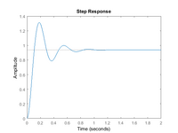
The classic proportional controller reacted to a step change in process variable by an initial overshoot followed by an undershoot and another smaller overshoot and undershoot.
It has been so many years since I set up a PID controller (temperature, not speed) that I forget the details of strategies to minimize the overshoot and undershoot.
As I recall, one method to reduce overshoot was to increase the proportional band drastically. Of course this approach is not applicable to power generation. (My memory may be faulty on this.)

Screenshot 2024-12-24 at 06-20-48 Control Tutorials for MATLAB and Simulink - Introduction PID...png
With diesel sets, the overshoot may be limited by the capacity of the prime mover.
I don't doubt your experience with the hydraulic unit. Possibly the dashpot was a form of derivative control.
The 'net says that adding derivative will decrease both overshoot and settling time.
A suggestion;
A hydraulic plant may have a large mass of moving water in the penstock.
Changing the loading on a set will require a change in the velocity of the water.
Changing the inertia of the moving mass of water may add control complications that are not seen with many other types of prime movers.
 
See https://mypdh.engineer/lessons/detailed-operation-of-the-governor/ for a detailed description of a governor compensation scheme as applied to a Diesel engine.

If applied to this governor, a dashpot bypass would bypass the needle valve, essentially disabling the compensation feature.

There was no derivative control applied to those hydraulic units; the governors were P + I only.

The compensation scheme, as you alluded to, was there to stabilize the unit speed against changes in water velocity, especially important prior to synchronization; once the unit was on line, though, its speed was determined by the grid, meaning it was virtually dead-bang constant, and all the compensation scheme would do under those conditions was retard the rate at which the wicket gates would move and therefore how quickly the unit could be loaded or unloaded. This became a hindrance when water flows were to be changed significantly on the hour in compliance with that day's peaking schedule but where no units were coming on line or being taken out of service.
 
At this point I’ve had to work on steam turbine governors, gas turbine governors, mechanical and digital hydro turbine governors, a diesel Woodward governor, and a battery control system. Not an expert at any of them, but one thing I can say for sure is they are all different.
We have two versions of digital PID hydro governors with different control schemes but the one thing in common is they are not true speed governors - when online the setpoint is gate, flow or power, and speed deviations are a bias, rather than the variable in control. Older mechanical fly ball governors in hydro were true speed control, proportional with temporary speed droop with a dash pot, at least on Francis turbines (temporary speed droop reduced the gain at higher frequency)
Permanent Droop was a cam that I believe unloaded the speed spring (which reduced speed setpoint) with gate feedback.
The gas and steam turbines are more classic proportional speed governors, but the speed governor is often overridden by other controls, such as temperature control for gas turbines and inlet pressure control for steam turbines. As an aside, We had to modify our load control on many of our gas turbines in order to prevent the power control function from overiding the normal droop response to frequency excursions.
The diesel uses a 2301E governor that’s always in droop, but is sent a bias signal from the Woodward engine controller to implement isochronous or load control - so even in isoc the governor itself was in droop, but the engine control would adjust the bias as needed to maintain frequency.
The battery was either in grid forming or grid following modes - in grid following is would take MW and MVAR commands, where’s in grid forming it acted like a generator and set the frequency and voltage.

My point in all this is to remind everyone that speed/load control on generators is implemented differently on different generating assets in different eras, and it’s not super accurate to generalize exactly how machines respond as their controls are all quite different.

My $0.02.
 
Maybe it is time for a review of the action of a droop governor.
When sets are operated in parallel, the droop is more of a load control than a speed control.
For easier explanation let's consider a hypothetical case where the governor is set to 10% droop.
The frequency is 60 Hz and is set by the grid.
The load is controlled by the speed setting,even though the set is not capable of changing the grid frequency by ore than an insignificant amount.
With the droop governor set to grid frequency, there is no power exported. The set is idling online.
With the 10% droop governor set at 61Hz, the set tries to speed up, but it cannot. Power output is 1/6 of rated capacity.
With the same governor set at 62Hz, the set tries to speed up, but it cannot. Power output is 1/3 of rated capacity.
With the same governor set at 63Hz, the set tries to speed up, but it cannot. Power output is 1/2 of rated capacity.
With the same governor set at 64Hz, the set tries to speed up, but it cannot. Power output is 2/3% of rated capacity.
With the same governor set at 65Hz, the set tries to speed up, but it cannot. Power output is 5/6% of rated capacity.
With the same governor set at 66Hz, the set tries to speed up, but it cannot. Power output is rated capacity.
When a block load is imposed on the grid, the grid frequency drops by an amount determined by the ratio of the load to the total output of the grid.
This is generally a very small amount of frequency drop.
The droop governors work together across the grid to supply the extra load demand.
Once the droop governors have increased the prime mover effort to accommodate this increased load, the drop in frequency is even less, but still slightly below the nominal 60 Hz.

Now, the swing set, an isochronous set, a load control panel or other means acts to correct the frequency back to the exact 60 Hz. (Or possibly slightly more in the case of cycle counting control.)
Any one set that is capable of accepting the full block load increase will be capable of correcting the frequency back to 60 Hz.
To pick up load on one set in a parallel group of generators, the governor set point is raised further above the nominal frequency.
 
Thanks for your explanation, CR.

A note on load control panels.
It has been stated by myself and others that isochronous sets do not work well together.
However, An isochronous load control panel will cause one set to act as the swing set by setting the governor setting of the set in question at enough higher than the settings of the droop governors to drive the frequency back to nominal.
That correction signal may be sent to more than one set.
That group of sets together will then act as the swing set.
The general statement;
"There may only be one isochronous set in a system."
Is more accurately stated as;
"There may only be one point of isochronous correction in a system, but that correction may be applied to more than one set."
 

Part and Inventory Search

Sponsor