Continue to Site

Eng-Tips is the largest engineering community on the Internet

Intelligent Work Forums for Engineering Professionals

  • Congratulations KootK on being selected by the Eng-Tips community for having the most helpful posts in the forums last week. Way to Go!

Isolation between two separate earthing systems and challenge of bonded structure between the two 3

Status
Not open for further replies.

OzGuy

Electrical
Apr 8, 2014
10
Hi,

There are two separate facilities with separate owners/operators and separate power systems, hence separate earthing which are not connected to each other.

There are metallic pipes running between the two facilities (say one side is the buyer and the other side is the supplier) where the pipe support and structures are bonded to earthing at both sides.

With this scenario the two earthing are practically connected via the steel structure and the pipes.

Are there any issues with this arrangement?

The challenge is that if there is a potential difference between the two earthing (e.g. due to a fault at one side) then the piping and structures will carry potentially huge currents. It can cause other hazards too.

Connecting the two earth systems via a cable or earthing conductor is not an option.

An option would be an insulating gasket (flange) be used for piping and the pipe support shall have some insulating pads to isolate them from the piping. Now the pipes at two sides are isolated. The pipe supports can be individually connected to the earthing, so the bonding is observed at both sides of the pipe. This way the two earthing system remain isolated - well, not directly connected via a metallic conductor.

the challenge would be more for installation in Hazardous Areas.

What are your thoughts?
 
Replies continue below

Recommended for you

See IEEE 80/2013 17.9 Transferred potentials
See Figure 46 —Transfer potential on a fence
If the fence potential stays under tolerable touch voltage, then far from the fence will be lesser.
If the ground fault current from one substation does not return, in some way, to the second substation this will be the touch voltage transferred.
If there is some interconnection, then part of the ground fault current may flow through the pipe and transfer the high voltage potential to the lower voltage substation.
See fig. 30
17.9.5 Piping

 
A lot of piping and structure will be a very low impedance path.
Any IR potential drop across the pipes and structures will be proportionately low.
If these are facilities rather than substations, then most ground fault currents will return via equipment grounding conductors.
Typically, very little ground fault current returns via the ground and grounding electrodes.
Substations, which are subject to remote faults to actual ground via transmission lines and distribution lines are a special case which I am not addressing here.
I would evaluate the worst case of touch voltages at each facility individually.
If there is a location where the possible touch voltage is too high, then that may be mitigated by equipment grounding conductors and/or more grounding electrodes.
(In some instances, more grounding electrodes at one location may make a touch voltage worse at another location.)
Once each individual facility is shown to be safe, then the other facility will act to lower the impedance to ground.
Any locations (building cladding, the actual interconnecting structure etc.) that show higher touch potentials may be addressed by additional equipment grounding conductors.


--------------------
Ohm's law
Not just a good idea;
It's the LAW!
 
OP said:
Connecting the two earth systems via a cable or earthing conductor is not an option.
here is a solution.
Identify the line of demarcation between the facilities.
You should be able to draw a dividing line somewhere on the structure to indicate where the two owner-ships meet.
An inch or so on each side of the demarcation line, drill or bolt terminations for additional equipment grounding conductors.
You may consider running jumpers to grounding straps on the piping.
Your interconnection between systems will be the very low impedance of an inch or so of structure between the independant ground connections.
Beware, the lower impedance to ground may not impact ground currents flowing on equipment grounding conductors, but it may increase the current flowing into and out of the grounding electrodes with an increase in possible touch voltages.

Another issue to consider;
The resistance or impedance to ground of the grounding electrodes.
The resistance to ground of the electrodes may be in the order of 1 Ohm to 25 Ohms.
Even at the lower end with 1 Ohm resistance, current returning through ground will pass through the added resistance of at least 1 Ohm.
A ground current over equipment grounding conductors in one facility may partially return through ground from the other facility.
In that case, the shared current will be passing through the resistance to earth of two sets of grounding electrodes.
Given the very low impedance of properly installed equipment grounding conductors, the added resistance of the path through earth will greatly reduce to extra return current.
It may be that the only instance where this is an issue is a fault to grounded metal at or near the connecting structure so that fault current divides towards both facilities.

--------------------
Ohm's law
Not just a good idea;
It's the LAW!
 
OP has not provided specifics of the two separate systems but there could be valid technical reasons for maintaining separation. One example is where the earth of an earth return system (eg. electrified rail) has to be separated from a system (eg TNS) where the earth only carries fault current. In this case, bonding the two together could result in normal currents flowing in the earth wiring that are expected (and required) to be current free. This would create an immediate hazard should earth wires be disconnected whilst current is flowing.

ozguy said:
An option would be an insulating gasket (flange) be used for piping and the pipe support shall have some insulating pads to isolate them from the piping. Now the pipes at two sides are isolated. The pipe supports can be individually connected to the earthing, so the bonding is observed at both sides of the pipe. This way the two earthing system remain isolated - well, not directly connected via a metallic conductor.

As per your suggestion, if isolation is required,
[ol 1]
[li]all interconnecting metalwork between the two systems needs to be isolated with an insulating gap[/li]
[li]two isolation/insulation gaps are necessary (perhaps 2.5m apart) to prevent a person bridging the two earths and being exposed to a potentially hazardous voltage difference between them under fault conditions[/li]
[li]for adjacent metalwork (eg. pipe and metallic support), isolation of all items should be colocated so that a person holding one side of the pipe can not bridge to the other side of the support frame[/li]
[/ol]
 
@7anoter4 @waross @EnzoAus

Thanks everyone for your help and I am very grateful for your contribution. All you have mentioned makes sense and really helped me understand.

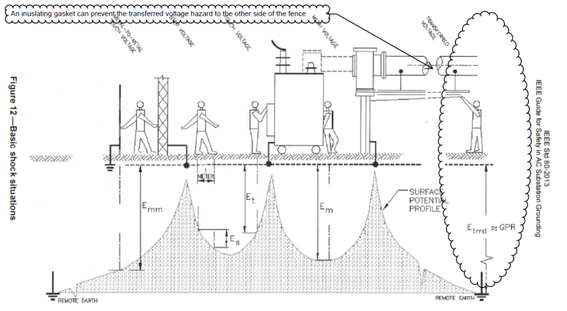
To me the transferred voltage is the key. Figure 12 clearly depicts how an uninsulated pipe/structure can propagate the hazard and how an insulating gasket can avoid it. And yes, the structure like pipe supports also shall be insulated.

Insulating_Gasket_Earthing_IEEE_80_l9807v.png
 
What voltages are you dealing with?
Do you have a substation involved?
It makes a difference.
Your diagram may not be applicable to your situation.
That Figure looks like an isolated phase bus rather than a pipe.
With 480 Volts you have 277 Volts to ground and relatively little touch potential hazard.
At distribution voltages the hazard increases.
The most serious installations are those involving transmission voltages.
Normally, ground fault currents on 480 Volt systems are conducted by the equipment grounding conductors.
Whatever touch potentials you may calculate for either plant individually, I would expect that common bonding through the connecting structure will lower those potentials due to the additional grounding acting to reduce the impedance to ground of both plants.
There may be exceptions for special cases.
ie: If one plant will have very much higher touch potentials then the other plant, then there may be some transference.
In that case it may be better to address the reasons for, and act to lower those high touch potentials in the plant of origin.


--------------------
Ohm's law
Not just a good idea;
It's the LAW!
 
Status
Not open for further replies.

Part and Inventory Search

Sponsor