Eng-Tips is the largest engineering community on the Internet

Intelligent Work Forums for Engineering Professionals

J Bolt Hanger for Walkway Stringer 1

Status
Not open for further replies.

bootlegend

Structural
Mar 1, 2005
289
0
16
US
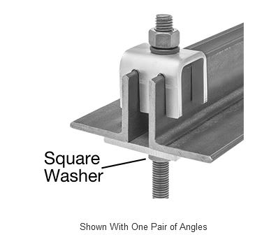
Has anyone "designed" a hanger like shown in the attached sketch? I've seen them used occasionally in mine processing plants but I assumed they were just remnants of decades old practices.

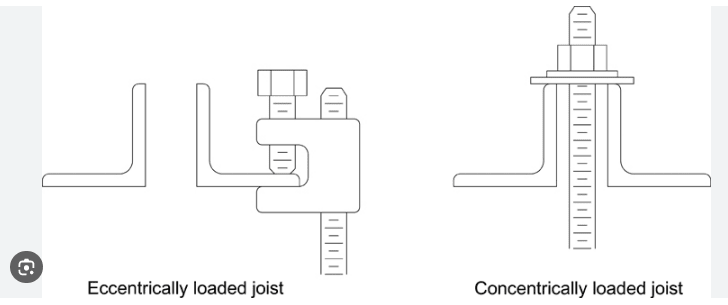
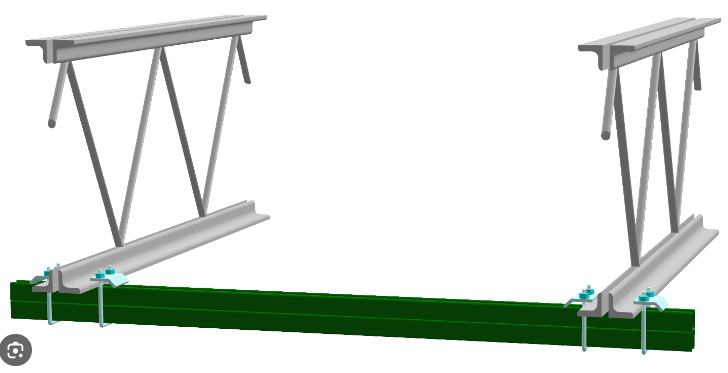
I've been asked to use this concept to support a walkway stringer from the bottom chord of a box truss conveyor. Typically I would have a bolt through the horizontal leg of the bottom chord and the horizontal leg of the stringer. I can get grade B7 J bolts but there's concentrated forces in the bend, shear and bending in addition to the tension. Applied load will be less than 4 kips so gut feeling is that it will probably work. Still, a quick image search online shows plenty of pics using the j bolt to clamp down a bar grating or such but none using it as a hanger. I need to put a capacity to the connection if I'm going to use it and that is making me lean toward avoiding the connection.

 
 https://files.engineering.com/getfile.aspx?folder=550dd2c1-7507-4b71-9da9-9a36f77c573f&file=walkway_hanger.pdf
Replies continue below

Recommended for you

I wouldn't. Unless I'm mistaken, those J-bolts are bent cold. So you're putting a sustained load on a knife edge on a strain hardened piece of steel. That's an abnormal use case and, while I can't say with 100% certainty that it'll fail, it gives me the willies.
 
While I wouldn't consider such a connection without a tested assembly, you could look at checking the bolt for bending (straightening). I expect a quick check would yield significantly less than 4 kips capacity, probably around the 1 kip range. Another thought on a quick check is look at the J-bolt as if it was an anchor in concrete with sustained tension, you would find around 1 kip capacity there as well, hence why J-bolts are rarely used for tension connections.

I did a quick simple check as follows:
Z = d^3/6 => 0.0407 in^3
e = inside bend radius/2 + d/2 = 2.1875" (I assumed bend radius sim to #5 rebar)
Omega = 1.67
(fy/z)/1.67 = F(e)
F is approx 1.17 kips.

There are other considerations for bending in round members as well, this is only the start of a much longer calculation. You will also need to check bearing, potential torsional effects, bending/torsion on the supporting members, etc. This being said, I wouldn't use this connection and would prefer a more typical method of attachment. Maybe even adding a tube in the angle and a U-bolt over the tube and 2 bolts in the supported hanging member.
 
McMaster-Carr has a variation on your hanger bolt that eliminates the bend, but not rated adequately. You could look around to see if some higher-rated version exists. McM only sells what somebody else makes. You would need to have the second vertical leg as part of your weldment.

hanger

l-hanger_k8wdyt.jpg
 
Thanks for all of the confirmations. I knew I didn't like the connection but I like to have a good reason for dismissing a contractor's request.

Those are some pretty useful connectors posted above if I had two angles. I also considered drilling an extra hole and using a large U-bolt but at that point it's just as easy to use a structural bolt through the bottom chord.

Thanks again for the comments.

 
Status
Not open for further replies.
Back
Top