Eng-Tips is the largest engineering community on the Internet

Intelligent Work Forums for Engineering Professionals

  • Congratulations waross on being selected by the Tek-Tips community for having the most helpful posts in the forums last week. Way to Go!

Jacket Cooling Water Bypass (Where/When to bypass?)

Status
Not open for further replies.

francis_mechanical

Mechanical
Aug 12, 2016
18
0
0
PH
I will be supplying a cooling water to an engine. I need to keep the water constant temp @ 30 degress celcius. My idea is to put a bypass after the supply pump and reciculate some of the water back to the heat exchanger to further cool the water.

Is this a good idea? Can you recommend another configuration?
 
Replies continue below

Recommended for you

Please draw or sketch this out so we can understand what you are trying to do.

Bypass mixing is common to maintain a fixed temperature, but it's not clear to me what this scheme looks like, where or how it is controlled or the relative location of coolers and engine.

Remember - More details = better answers
Also: If you get a response it's polite to respond to it.
 
are you desiring the Inlet or Outlet to be maintained at 30C.

most automotive engines have a bypass at the engine jacket outlet back to the pump suction. this keeps a flushing flow through the jacket to avoid hot spots downing initial warmup. given the thermostat is near the bypass (if not regulating bypass), it also keeps it at the exiting coolant temp and tries to regulate the Outlet at desired
 
Hi! Here is a draft of the PID. You can see that its not finish yet. Since I have to study more about the system like...

1. Proper/Ideal position of the expansion tank (if necessary)
2. How to draw my idea on how do the temperature leaving the the engine would control the control valve.
3. Overall, this drawing is on its early stage, and help and suggestion would be very helpful :-D.

My plans are,

1. Control the control valve using the temperature condition leaving the engine.
2. For the cooling tower, maintain the cold water temperature by controlling the fan speed or using some bypass (any suggestion?). For now, my idea is to control the water leaving the cooling tower by varying the fan speed using VFD.

I still have to learn about instrumentation stuffs and how to draw my idea on PID
I'm not new in thermodynamics and heat energy things. So my final question - Am I on the right track on designing the system?

The idea is simple, just carry away the heat from the engine jacket by using 2 circuits and dispose it to the air.

See Attachments for the PID (Thanks for the initial response)
 
 http://files.engineering.com/getfile.aspx?folder=82ba1217-c63c-471e-95f4-2828cde32afa&file=Engine_Cooling_System-Model.pdf
I just thought, maybe I can control the temperature of water leaving the cooling tower by reducing the flow of hot water entering the tower and still supply the same flow-rate of water in the pumps since the cooling tower has a basin.
 
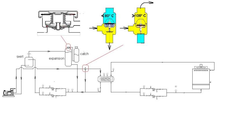
i would think designing the system the other way around would be more useful. what you actually want is not a specific inlet water temperature, but a flow of water through the engine that is sufficient to absorb the heat you need to get rid off, with some extra capacity. thus i would regulate the water outlet temperature of the engine with a thermostat in such a way that the optimal engine temperature is reached and regulated under all foreseeable operating conditions. that usually means that the outlet temperature (in a pressurized system) can be quite high, say somewhere between 95 to 105 C, depending on the pressure build up in the system when the water heats up. if the temperature gets higher then the thermostat setting, part of the flow then is directed to and through the heat exchanger, cooled down there, and flowing back to the engine. as long as that water return temperature is such that the resulting mixture in the engine is capable of taking the heat away as needed, you will be fine. it does not matter whether the water coming back from the heat exchanger is 30, 50, or 70 C, as long as the thermostat is capable of regulating the outgoing water temperature in the engine within it's range.

the heat exchanger that gives off the heat to be cooled away to the cooling tower system thus functions like the radiator in a car. in the cooling tower circuit another valve then needs to be incorporated so that the water flowing through the engine never gets out of the range that can be controlled by the engine thermostat. there a quite different setting could possibly be used, depending on both the capacity of the cooling tower and the need to keep the water returned to the engine within a particular range.

the idea is to control the engine cooling system with two thermostats in tandem. the primary regulation takes place in the engine itself, and when temperatures go beyond the range foreseen the additional thermostat comes into action. you can compare it to a system in a car where the fan or fans are actuated electrically when the airflow through the radiator is temporarily insufficient, eg in slow traffic or standstill after a prolonged high speed drive.

you are free to mount the expansion tank for the engine cooling system anywhere, since it is a closed and pressurized system. usually the cooling tower system is not pressurized and "open", although a expansion tank may be added to prevent contact with air that could lead to oxidation of coolant additives or antifreeze components when used.
 
This seems a bit complex to me.

don't really understand why you have the intermediate water/water HX and don't just stick in an air cooled radiator (like a car).

however if you control the bypsass flow on the temperature going into the pumps using your bypass then this will work quite well providing the flow rates work out OK. To warm up 90-100 % of flow goes via the bypass, full power 100% goes via the HX and everything else is somewhere in between.

I would just make your cooling system a single speed system or maybe use parallel umps to get two flow rates. Circulation pumps like this are usually quite low power and temperature of the water is really dependant on air temp and humidity. you also want your two temperature controlling elements not to fight each other and avoid temperature "hunting" and wild swings between full flow and low flow. Thermal circuits like this have a time lag and it can be difficult for systems to stabilise unless one is essentially fixed or very slow to change.

I would be tempted to put your circulation pumps on the primary circuit downstream the HX simply to reduce operating temp on the pump. No need to stress the pump if you don't need it. Pressurisation is often as you've got it - just before the inlet to the pump

Remember - More details = better answers
Also: If you get a response it's polite to respond to it.
 
@romke

i really wanted to as much as possible, provide constant amount of water (flowrate) on the heat exchanger both from the first circuit and the 2nd circuit. Im thinking I would have a huge change in cooling water temperature across the engine if I would supply less flowrate and I dont want my system to be handling large temperatures. the engine data tells that cooling water are leaving the engine less than or equal to 85 degress celcius. Can you give a drawing of the your circuit idea? Thanks.

@LittleInch

"don't really understand why you have the intermediate water/water HX and don't just stick in an air cooled radiator (like a car)"
I would really love to have my system using radiator coolers, the honest answer to this is that, I have less knowledge to design the radiator cooler, I know I can do it but time for submission of this design is an issue. I still have to study more about radiator coolers, and I find it hard to find references on the internet. So, yes I want to have a radiator cooler but, I that would require more time since I still have to do more research. This system im designing right now will not be constructed. Im planning for my next project to design a cooling system that includes radiator cooler and this project will be for construction. Can you help me find references on designing radiator coolers?

"I would be tempted to put your circulation pumps on the primary circuit downstream the HX simply to reduce operating temp on the pump."
I think this is really helpful. I decided to put the pump before the heat exchanger is to provide more pressure because Im thinking there would be a large pressure drop on the HX. But I want to consider transferring the pump base on your comment that my pumps will be subjected to high temperature (honestly, I forgot about the thermal stress).

I will update you guys for my design and Id love to have more constructive criticism :-D

Thanks.
 
some of my thoughs
1) the pumps should be on the cold coolant side and take there suction from the bottom of the heat exchanger. thus on a low coolant condition, the pumps would be provided. also hot coolant will be more likely to cause pump cavitation due to steam flash
2) the pump discharge should go through a Swirl Tank to reduce any entrained air from the coolant. the swirl should be at coolant system high level
3) the swirl is vented through orifice to the expansion tank. the expansion tank should have a closed system pressure cap. the cap relief will go to a catch tank. the expansion tank drain will be to pump suction. the level in the expansion tank will control the coolant pressure as temperture changes. if an expansion volume of air is used, the pressure will build propertional to temperture. if there is no air volume (solid coolant), the pressure will be maintained by the cap relieving spring at a constant. thus the pressure relief will be on the low pressure side of the coolant. this should keep the pumps from have suction flashing. but the engine discharge pressure will be higher and so will the coolants boiling point
4) use a wax pellet thermostat design with bypass.
5) not shown, but a high point orificed vent on the Hx shell to the expansion tank would be needed

eng_tip_tsmrii.jpg
 
Putting the bypass valve in the cooling tower water circuit to bypass the heat exchanger would be better. Modulate this bypass to control the jacket water temperature. You would also need a bypass valve to bypass the cooling tower, directing the cooling tower directly to the sump. This bypass valve should open to the sump when cooling tower water drops to 40F and it should not open until cooling tower water is say 65F and above to protect freezing of condenser water. The cooling tower sump should be heated during winter.
 
So can you tell us why only the current jacket water cooling circuit on this engine doesnt work,( which probably has driven you to explore this alternate cooling option) while the engine lube oil cooling circuit does ?
 
I'm not sure what manufacturer your engine is, but for example CAT engines have cooling system installation manuals, where they run through basically everything you need to consider in setting up the engine cooling system (layouts, inlet vs outlet controlled cooling systems - and what that means for the system requirements, etc).

You can definitely find CAT's generator cooling system installation guide by googling exactly that phrase. Most manufacturers should have a similar document, and they should be able to provide that to you if you are purchasing the engine from them (normally they are more than happy to assist with installations from my previous experience). It's a great reference document for these kinds of activities.

Your application sounds a little different, but since you mentioned you're new to this it would be pretty useful to study one of these documents for a day or so.
 
Status
Not open for further replies.
Back
Top