Continue to Site

Eng-Tips is the largest engineering community on the Internet

Intelligent Work Forums for Engineering Professionals

  • Congratulations KootK on being selected by the Eng-Tips community for having the most helpful posts in the forums last week. Way to Go!

Jacking Pit Design 7

Status
Not open for further replies.

babibibak

Civil/Environmental
Apr 27, 2020
12
Hi fellows,

I am working on project that requires a design for jacking and receiving pit. I have no problem designing the retaining wall to resist the active load and reach bottom of the pit. The problem is the jacking load is 2,000 kips. The maximum concrete block we can install is 18ft X 20ft and the maximum passive pressure that the geotech has recommended is 3000 psf max. When you do the math there is 2.6 ksf (2000kip/18X20 - 3 ksf)of pressure remains to be resisted by retaining wall. The way I design it, I use LPILE and distributed load to come up with a CIDH design. The problem is the CIDH is like 4ft DIA. @ 5 ft OC. and even with maximum reinforcement the deflection is excessive. Any recommendation on how to design jacking pit with such a huge load?
 
Replies continue below

Recommended for you

I don't think you can (I would not) double the width of a wall for calculating passive resistance - a soldier beam's embedded flange width or concreted drill hole diameter, or a relatively narrow deadman, yes; but not a wall. Walls are designed on a LF basis. You can't have separate resistances for the wall and the soil behind it. Sheeting walls are considered flexible and allow you to apply/distribute the applied jacking load to the soil. I would use the passive resistance only. I believe that your problem is related to lousy soil properties recommended by the Geotech. Don't be afraid to question the Geotech. I rarely use the Geotech's recommendations for soil properties.

 
I think in this case that Geotech is conservative, it is reasonable to assume the passive width to be twice the width of wall. This can compensate for their conservatism.
 
Just consider the whole wall as a single pile. The passive width per Caltrans can be as high as twice the pile diameter. Also, in my case the passive pressure is 300 psf/ft which is 600 psf at the bottom of the wall. Essentially, twice as much as given by Geotech.
 
A wall is not a soldier beam. Soldier beams are "distinct vertical members" for which the passive resistance is commonly calculated using about 2 to 3 times the flange width of a driven beam or 2 to 3 times the width of the concreted embedment of a drilled-in soldier beam. Walls do not have twice their width for calculation of passive resistance. Walls are considered "continuous members" that are designed on a LF basis.

 
All very useful info for the original poster and educational for all. Thanks to PEinc.
 
PEinc Could you please share the pressure diagram you have used to design the sheet pile?
 
As this old guy looks at this, it seems solving the design needs input from someone similar to PEinc. His increasing the allowable passive pressure a geotech might give (which is maybe including a safety factor) means a very experienced geotech is needed. Ya can't beat actual experience, as PEinc demonstrates. I question the spread out of pressure from a wall as one would do for a single pile resisting lateral loading.
 
I think the resistance block is wider than the wall, in the way similar to a concrete square deadman. The wall is huge in our thought, but small in the earth. The problem is the influence will spread wider, thus affects the adjacent structures.
 
Comment on load spread. Let's say the resistance block is 50 feet long. You don't double the resistance of this wall as you would for a single pile. Yes, you add some benefit to the ends and bottom, but rather limited.
Edit: My resistance block is the concrete, not any soil behind it.
 
I am thinking the failure wedge is a 3D view. The passive pressure behind the wall remains as the given (3000 psf), but the failure plane at wall edge will flare out an angle, maybe equal to friction angle of the soil, thus the total resistance is increased to an extent due to increase in volume. But it's not as simple as the OP suggested - two times of the wall width, which don't seem have any literature supports it.
 
I agree with OG. At some increasing length, a narrow block stops being considered an individual heel block and becomes a continuous wall. But at what length? Therefore, to me, my reaction block should be treated as a wall for my particular design and I consider mobilizing only the width of soil immediately behind the block.

babibibak, as you requested, here are some hand sketches of pressure distributions that I used on the Ivy League project for the theoretical, triangular, passive pressure behind the block and for the trapezoidal passive resistance distribution that I invented(?) and believe is more representative of the situation than is the triangular distribution. But, remember, I checked both distributions.


www.PeirceEngineering.com
 
 https://files.engineering.com/getfile.aspx?folder=08e3b928-5c1d-4348-9239-f77e155b3748&file=Pressure_Diagrams_for_E-T.pdf
At some increasing length, a narrow block stops being considered an individual heel block and becomes a continuous wall. But at what length?

I fully agree with the message delivered above. However, for a rigid block (much rigid than conventional wall), with well positioned push forces to create effect on a serious of individual pile, what will happen behind the wall deep into the earth? I envision some extra soil body could be mobilized and utilized, but maybe too small, especially for this case with that much of deficit.
 
PEinc Thank you so much for sharing the information. The soil I am dealing with is a cohesive soil with 800 psf of cohesion and 0 friction angle. Even finite element analysis show 800 kip-ft/ft of moment in wall itself. I think I go with a CIDH design to resist the load and make sure the load is properly resisted.
 
Your statement " trapezoidal passive resistance distribution that I invented(?)" is not quite true. That trapezoidal distribution comes from Terzaghi & Peck I think. Your diagrams explain much better how your reaction block AND SHEET PILES worked.
 
Getting interesting now. For Ø=0, K[sub]p[/sub]=1, and p[sub]p[/sub]= 2c√K[sub]p[/sub]. So, for c = 800 psf, the passive pressure can be utilized = 1600 psf?
 
OG, I can't say for sure, but I don't think T&P ever used a trapezoidal distribution for passive pressure and I don't think that you will find the method I used in any soils or foundations text books. Yes, my trapezoidal distribution is a reaction or resistance, not an active or at-rest driving force. It assumes that the SSP is being pushed against the soil behind the SSP. I did not design a "SSP wall" to resist the jack load. I designed a very large "heel block" or "deadman."

 
Hey, ya got me on this one. However, a Fed report: FHWA-RD-75-129 "Lateral Support Systems and Underpinning" April 1976 indicates that passive pressures developed are roughly similar patterns to those measured as active pressures.

So that might be some backing info for you; who knows.

Some added comment. Take the case of a bull-dozer shoving granular material by pushing into a bank. At failure and movement is starting, the stuff moved is not usually much of anywhere off to the side of the moving block, being only directly ahead of the blade. Puts support to the assumptions used here.
 
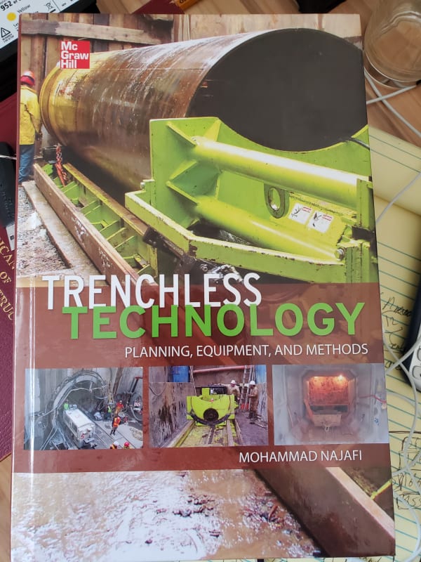
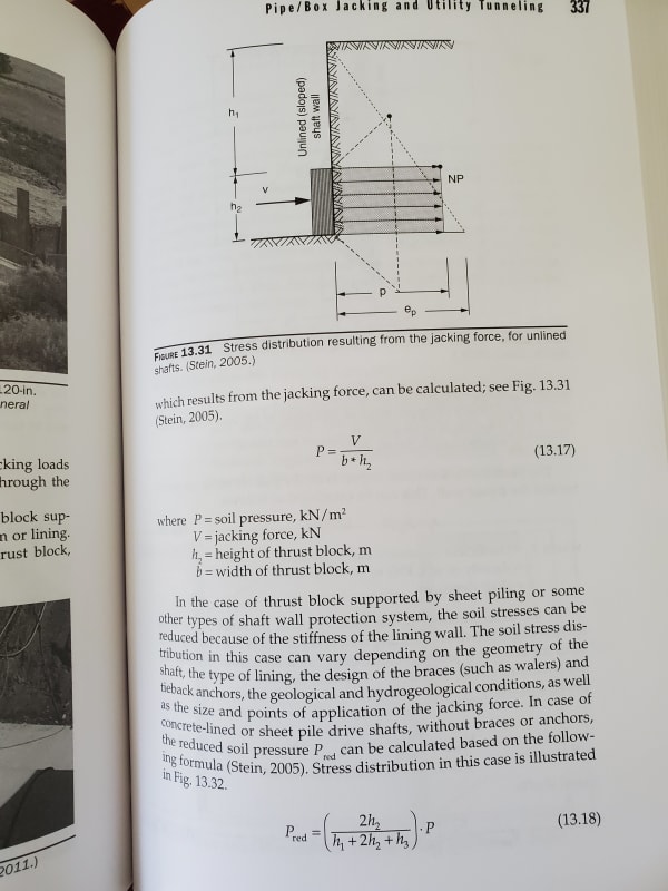
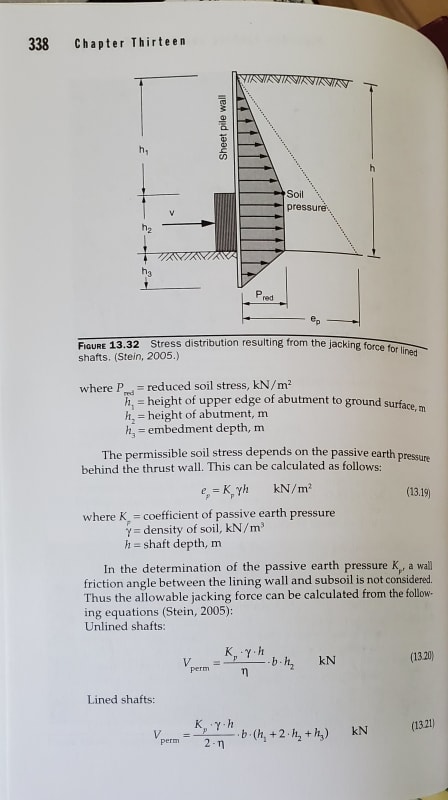
The trapezoidal pressure is actually presented in the book called "Trecnhless Technology" by Mohammad Najafi. I am going to determine the embedment by the equation and check the sheet pile for flexural. PEinc this is consistent with what you have done. Well done!

20200429_155520_se6fpd.jpg

20200429_155439_fjqu4i.jpg

20200429_155457_ew6ou9.jpg
 
Nice. I never saw that book. It's great to know there actually is a reference. Thank you.

It looks like the book is not using wall friction. That will have a big effect on your design.

EDIT: Just bought a used copy of the book on Amazon. I hope I get my $40's worth.

 
Status
Not open for further replies.

Part and Inventory Search

Sponsor