Continue to Site

Eng-Tips is the largest engineering community on the Internet

Intelligent Work Forums for Engineering Professionals

  • Congratulations MintJulep on being selected by the Eng-Tips community for having the most helpful posts in the forums last week. Way to Go!

JIB CRANE LOAD TEST FAIL, NEED ADVISE 6

Status
Not open for further replies.

Dat Tran

Mechanical
Jun 6, 2024
11
Dear all,

Please help me on this issue.

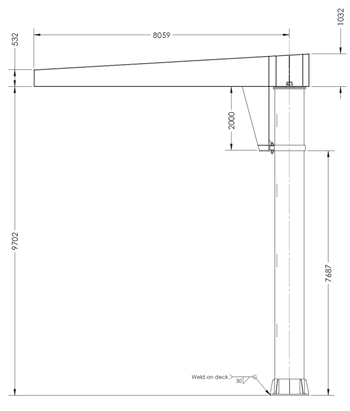
i did load-testing for Jib Crane, some information as :
Lifting height: 9.5 meters
Crane radius : 8 meters
SWL : 3 ton
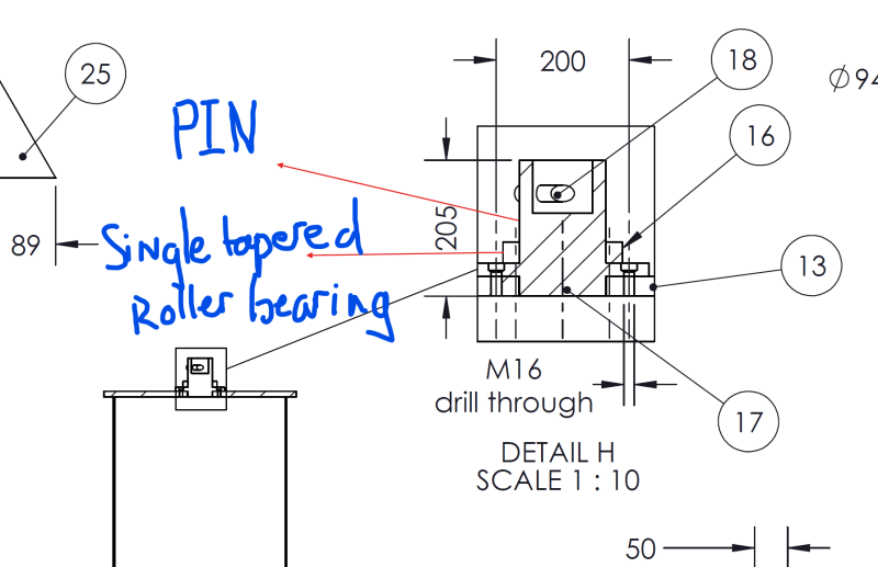
Screenshot_2024-06-06_142922_tzeikf.png
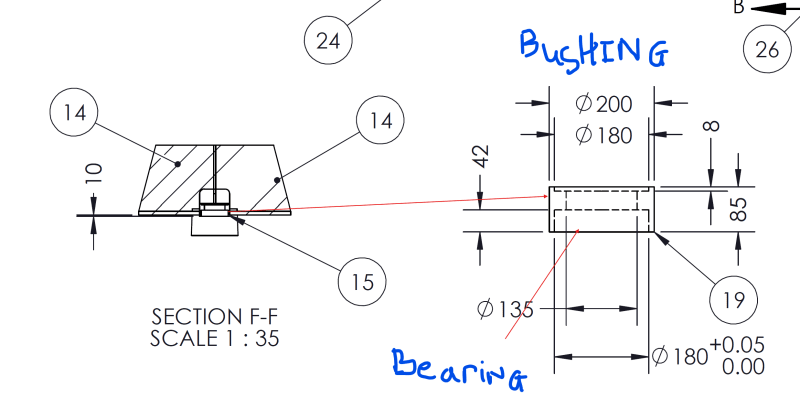
Screenshot_2024-06-06_143248_hugtkf.png
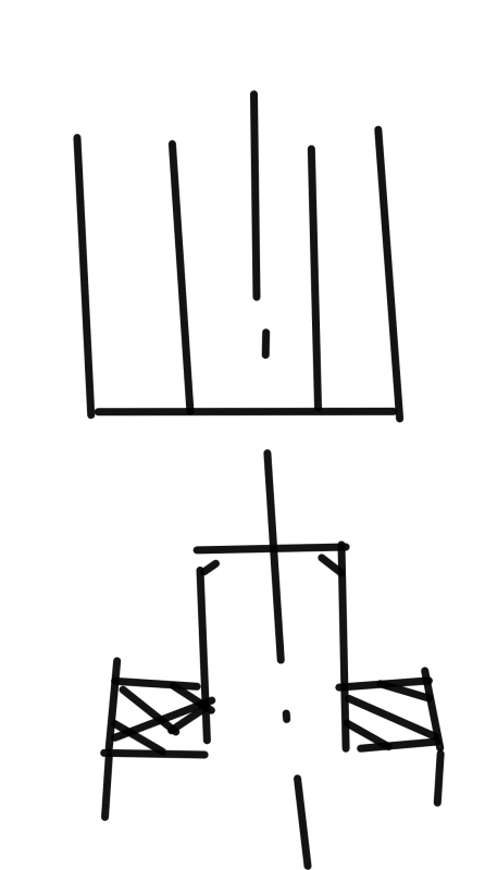
Screenshot_2024-06-06_143445_ad2ahw.png

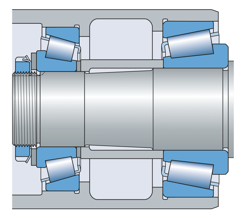
Single tapered roller bearing : dynamic load : 245 kN, static load : 365 kN
I used single tapered roller bearing (SKF) with pin and bushing (material SC45 + PWHT) for rotating (see above pic), i applied 1.25 x SWL and do load test but crane boom sags down when the load reaches the 7.5-meter, i assume the bearing selection was not correct, should i change?
Appreciate for your advise and support.
 
Replies continue below

Recommended for you

3DDave: OP's contour plots from their Ansys FEA are likely black because they have the outlines of each element plotted as well as the contours of stress/deflection, and the mesh is fine enough that when zoomed out this far, all you see is the black outlines.

Dat Tran: When you're plotting your FEA results, don't turn the element outlines on when zoomed out. I only turn those on when zoomed in on a localized stress to show how the stress relates to the mesh and check if the results are or are not mesh independent. I'll also reiterate what others have said: if you haven't already verified your model properly (hand calcs and/or adequate physical testing), don't rely on the results for anything.
 
I actually with 3ddave on this one.
The bearing is being miss used.
The bearing need to do work in the free state.
A male and female support that are precision ground, withd slip fit to rotate freely.
Then maybe a large thrust bearing.
This type bearing seems to me is not correct. Correct me if I am not correct.
 
Also the support.gib, Seems to should be 45 degrees for better leverage.or support
 
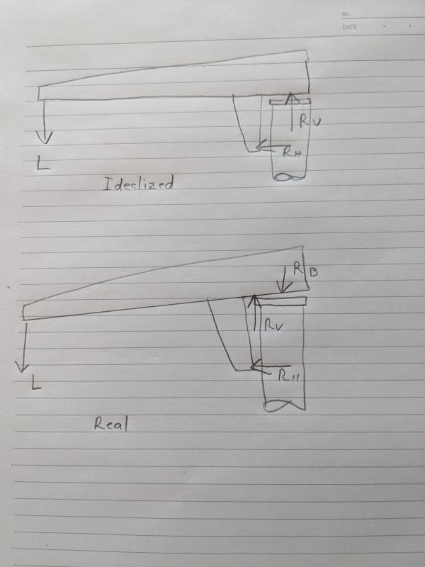
I guess this:

PXL_20240607_004402715_s6mmcc.jpg


Lack of stiffness (i.e. free play) in the single bearing. Solution as suggested by geesaman.d.
 
There should be two horizontal reactions. One at the upper bearing opposing the one at the lower bearing.

It doesn't look like the model is prying the top bearing like a bottle cap. That would be around an 80:1 lever.
 
@all: structure calculation is sufficient for load test, base metal is A572-50/yield strength 355 MPa, column OD 914 x 8mm thickness. Base plate 40mm, crane boom thickness 16mm. Pin & Wheel is S45C + PWHT.

LittleInch: jib crane is sufficient with load test at 7 meters point of crane boom length, when it reached 7.5 meters, it sagged down as picture of MintJulep. No bending occurs during loadtest.

SWComposites: Yes, structure calculation is sufficient for SWL.

Tmoose: Normally, max deflection shall be L/100. Failed result is crane boom sagged down but not bended down. That is the reason i assumed rotating mechanism got problem.

3DDave: column OD and thickness are sufficient for this load. Deflection is very less.

Stick: yes, noted. Thank you so much.

Guys: there is a reference video of jib crane SWL 2 ton installed using single tapered bearing on youtube, same mechanism with mine, "Gorbel jib crane installation part 1 and 2" from abom79.

MintJulep: yes, that is exactly what happened during load-test.


For contact to happen the top plate has to twist out of plane or for the vertical bearing holder to bend, either likely due to the side load that is represented by a 4:1 leverage of the applied force. The abom unit appears to have only 3:1 leverage, making for smaller side loads. See (time stamp 46:49)

"3DDave: column OD and thickness are sufficient for this load. Deflection is very less."

I have no idea what that means. What is very less? How many degrees does the column section between the bearings rotate relative to the floor?

Just to help the rest of us out, turn off the boundaries as previously suggested and show an orthogonal side view with the displacement colors and legend.
 
added a thrust bearing above single tapered bearing will resist the movement of wheels at rib. And 2 bearings will handle all the forces, moments,

The most resistant for prying moment is 2 wheels at rib support. Which is supportive to the top bearing to focus on rotating mechanism, and the rest of prying moment is the reason why i used tapered bearing, this single tapered roller bearing construction accommodates combined loads and provides low friction during operation.

Correct me if i am wrong,

Thank you all for your advise.

 
I really can't understand the bearing and bushing arrangement from the drawings that you've provided so far.

The Gorbel crane in the referenced video is 2/3 the load rating and maybe half the boom length.

You have a 90 mm bearing radius and a 8000 mm load radius. Any play in the bearing is amplified by 8000/90 = 88 times at the end of the boom.

Something like this would let you adjust the bearing preload and remove the play.

0901d196805ecdd2_png_highpreview_800_omls6d.png
 
3DDave: This seems a bit illogical, but the truth is my PC crashed just last month, and all files were lost. Let me do again and bring up here.

MintJulep: yes, agreed.
 
Then back to beam formulas and free body diagrams.
 
My point and this link provides the data from skf pdf
Roller bearing can have radial preload.
Thrust bearing require axial preload.
In my previous statement I misstatements, bearing should of being in free state. I actual gave geesmand a star because he was correct.
My statement the application of the bearing used is not proper.
 
Check out this lecture on YouTube very well is
Specific on a situation like this tell me your thoughts

Search on youtube

Lecture 18 combined axial and radial loads on bearings
 
Status
Not open for further replies.

Part and Inventory Search

Sponsor