Continue to Site

Eng-Tips is the largest engineering community on the Internet

Intelligent Work Forums for Engineering Professionals

  • Congratulations SSS148 on being selected by the Eng-Tips community for having the most helpful posts in the forums last week. Way to Go!

Jiggling in speed governing system of Siemens steam turbine 1

Status
Not open for further replies.

machengr

Materials
Jun 1, 2019
4
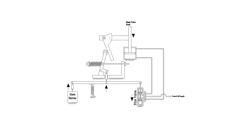
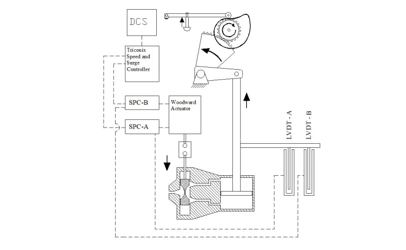
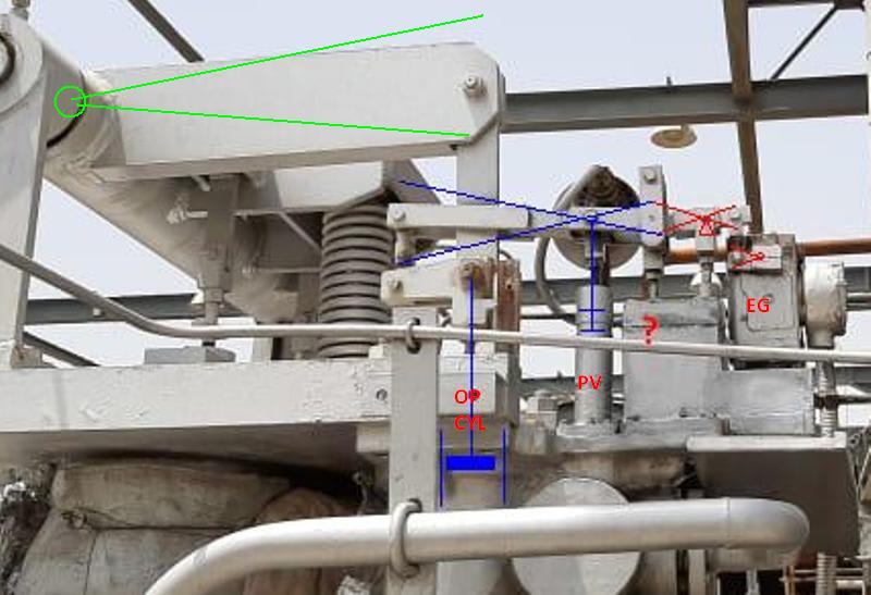
We are facing problem of severe jiggling on steam inlet control valves’ servomotor assembly of a process critical steam turbine of make M/s Delaval (Now Siemens). These valves are operated by a woodward EG10-P actuator as per governor inputs.

All the pilot valves and pistons of the servocylinder amplifying assembly are moving up and down very frequently to maintain the appropriate steam inlet flow to maintain the speed of turbine (video attached). Speed variation of ~ 8 RPM is persisting at whatever speed of turbine we have tried between 9300 to 9500 RPM.

Following actions have been taken so far to analyse the problem:

1. Speed of the turbine was decreased / increased but the amplitude and frequency of control valves' jiggling remains the same.

2. Temperature of lube oil / control oil header was increased from 45.5 to 49 0C – No change in jiggling. This oil drives the actuator EG-10P and also serves as hydraulic amplification oil in the servocylinder assembly.

3. Control oil pressure increased from 10.4 to 10.8 kg/cm2 – No change in jiggling

4. Air was bleeded from control oil filter and later, filter was changed over to standby one – No change in jiggling

Please share your opinion about the following questions:

1. What can be the possible cause of such highly frequent jiggling in EG-10 P actuator and servocylinder assembly?

2. Can we check the health of EG-10 P actuator while in operation by evaluating communication between governor and actuator in terms of current / voltage?

3. Can such problem occur due to air trap inside EG-10 P actuator?

4. What directional steps can you suggest to reduce this phenomena?
 
Replies continue below

Recommended for you

I don't woodwards, but I'll reply to what might be common to other systems
First would be verify the "demand" signal to the EG10-P electronics is stable.
Not knowing the gains, I have seen a digital process demand flickering 1 bit put noiz into the turbine governor.

You would need to know the gains to determine expected magnitudes, but can you measure the EG10-P stem travel.
that would be to see if the problem is the rest of the linkage/hydrualics are doing what they told to.

I have also seen a lot of "stick/slip" in the linkage for the steam valve actuator

could you post a lever or control diagram to farther any discusions
 
You did not mention if this is occurring with the turbine loaded or unloaded. And, I didn't see anything to tell what the turbine is driving. If this is occurring when unloaded, it may be normal and not a problem. What would you consider an acceptable amount of speed variation?

Our newest steam turbine drives a generator. That machine has about a 15 rpm hunt at the generator when running unloaded. As soon as the generator is synchronized, the hunt stops and the governor holds speed to within about 2 rpm. Your video was not attached, so I don't know the frequency of the oscillation. I have included a portion of a plot to show how our governor controls when the load in removed and then reintroduced.
Capture_lcioh8.jpg


Johnny Pellin
 
Dear byrdj,

Thanks for your post. There is no issue with the demand which is actually the speed of turbine measured by three speed probes.

I am also interested about adjusting gains but that is the domain of our instrumentation team who are not taking risk as the turbine can trip and the whole fertilizer plant will trip in fact.

All the linkage assemblies are free to rotate and do not have play.

Here is the picture of link assembly.
20190512_111010_vfjhml.jpg
 
Dear JJPelin,

Your point is valid but the turbine is running at almost full load. It is driving an ambient air centrifugal compressor. Current magnitude of speeed variation ~ 10 - 15 RPM is affordable but the very frequent motion of the complete linkage assemblies is a threat of rapid wear of internal components / failure. The linkage assembly has two parts: 1. pilot valve plunger + piston assembly 2. Amplifier pilot valve and piston assembly.

We are unable to check the response at no load because it is not possible to unload the turbine due to plant requirement. In case, it could be offloaded, I will let you know the results.

Do you think that the governor is too sensitive that it may be responding too fast to control any internal wear / tear / bypassing in the components of hydraulic servocylinder assembly?
 
My points above are not valid since you are running at high load. Thanks for providing the picture. This linkage is much more complicated that any at my facility. I would be interested to know what each of the five items connected to that horizontal linkage are. One would be the fixed pivot point. One would be the primary servo. One would be the pilot valve. And, one would be a position sensor (LVDT or equivalent) I have not figured out which is which and what might be the fifth item. I made up diagrams for my turbine linkages to make it more clear what was what. I have attached a couple of examples. Do you have something similar for your linkage?

T17C1Linkage_mplb0w.jpg


29C1Linkage_i8ixt0.jpg


I would check the calibration and adjustment of the position sensor(s). It is possible that the governor is adjusted to be too sensitive. You would need to consult with Woodward to understand your options there.

Johnny Pellin
 
A control diagram like Johnny P has show example would be nice.
can you measure the current to the EG and determine in there is an alternating component that would be demanding the EG to resond,

Your EG should be recieving a speed referance signal from some process controller to requext the speed. that is the input signal I was referning to.

Does the EG have the capabilibilty to go into open loop control ie manual of load limiting so the current signal to the EG is held constant Operator would just need to monitor the process and make changes to maintain control

et_r2_pahpfi.jpg


I'm guessing the "?" is a dashpot OR a shut down over ride piston
 
Dear byrdj and JJPellin,

Thanks for your responses.

Here are the drawing screenshots of servo assembly. Following is the arrangement:
EG-10P Actuator > Relay Pilot Valve > Relay Piston > Amplifier Pilot Valve > Amplifier Piston > Steam Control Lift

The process is being controlled by DCS and Triconex speed and surge controller.
The current input to EG-10P is around 153 mA out of 0-180 mA signal range. There is continuous variation of 0.3 mA in the current. The input current to actuator can be made constant but as byrdj told, the process will have to be controlled manually which is very risky for our process and can cause complete shutdown of our plant.

1. This is why I need your expert opinion to determine what can be the consequence of making input current to EG-10P constant and should we attempt it or not.

2. Moreover, can we make minor changes in the PID of speed controller to make the governor response sluggish?

3. In your opinion what can be the source of this very high frequency but low magnitude movement of whole servoassembly...mechanical internals of servo like ports and lands of pilot valves, rubbing of any piston etc or the EG-10P actuator may be getting varying signal or there is some internal defect in the actuator itself..?

Control_Diagram_apeql9.jpg


Servo_blhhow.jpg
 
The entire thing looks like a tuning problem to me. If you lock the input signal to the governor at a fixed value and the movement stops, it is likely a problem with whatever controller is sending the signal to the governor. I assume this is a cascaded pressure or flow controller. If the movement continues, then it is likely a tuning issue with the governor. I would consider it very low risk to lock the input signal to the governor for testing purposes. This would only lock the set-point of the governor which would still control to constant speed. I am not aware of any processes where running at constant speed for a few minutes would be a big problem. But, I don't know your process.

Because this is a speed and surge controller, there may be additional problems if you try to make the governor response more sluggish. The surge control function needs to be able to respond quickly. It is more likely that you would want to make the controller that is sending the signal to the governor respond more sluggishly. I am not an expert on tuning instrument loops. But, that is what I would suspect.

Johnny Pellin
 
(I didn't think about two stages of hydrualic relays)

I would think our electronic governor would be in a closed loop with speed feedback so whether or the ~8 rpms are causing the 0.3mA jiggles needs to be elimenated to farther the search for the jiggle, I have seen the process demand signal into the governor circuits have noiz. have you measured that signal to see if it is clean. If that signal is anolog, I have had good results by add a capacitor as a filter.

et_r3_eebr8c.jpg


Most of my career challanges for such jiggle has been with the mechanical linkages. Just a small amount of "stick", that breaks free alone with just a little amount of free play will go into forced oscilations. this type of problem was not limited to the small levers and links, but would include the larger bushing on the valve gear turn rod

Have you tried appling lubricant on the connections? However, when linkage gets into a forced oscillation it needs an abrupt change to break the cycles
 
do you know the "over travels" in the hydrualics from the EG to the CV stem lifts.
the reason I am asking, if you compare the servo demand fluctuation to the actual valve stem movements.

just assume there is 10% CEOT and OEOT in your setup, thus 80% of the eg stroke will give 100% steam valve stroke
thus 0.3mA/150mA should stroke the steam valve only 0.2%. If your actual movement is more, then the source is stick/slip in the hydrulic's linkage.

now that you informed about the two pistons, the lever connection I marked with "?" reminds me of a link I use to have problems with for GE UT70 controls. the connection had to allow for the opposing lever arcing. getting that connector smmoth took careful acssembly
 
You noted that you increased the oil temperature to try to decrease oscillations (jiggling). I suggest lowering the temperature, if possible. A lower temperature will increase damping in the oil system.

Best of luck!
 
Have you called your Delaval-Siemens representative or district manager?
If not, why not? That is what they are hired to do.
 
Not really related to the jiggle, but was the control oil temp actually being changed or is it just the oil suppled to the bearings. the mechanical turbine controls I worked, the operating/control oil was at the bearing drain temp.

Now the units with seperated HPU, yes, the temp could be controlled
 

Just wondering if still in service or was unit forced down?
 
Status
Not open for further replies.

Part and Inventory Search

Sponsor