Continue to Site

Eng-Tips is the largest engineering community on the Internet

Intelligent Work Forums for Engineering Professionals

  • Congratulations KootK on being selected by the Eng-Tips community for having the most helpful posts in the forums last week. Way to Go!

Job abortion - crack propagation analysis of cvd coating

Status
Not open for further replies.

Low12

Mechanical
Nov 20, 2019
22
Hey,

i am currently simulating the rockwell test on a Diamond coated Substrate (2D). I am interested in the Delamination process, but also the crack Initiation and Propagation within the Coating. I managed to simulate a crack in the Coating using the XFEM enrivonment, but unfortunately the Simulation Aborts after 2 cells have been seperated by the crack. I would like the Simulation to Keep running until the end - or at least a bit longer so i can see how the crack develops over time. The error Abaqus gives me is just the following : System error in timeup. Dtime=zero

I am using Maxps Damage, Power Law for Damage Evolution and a stabilization coefficient.

I would like to know what are the Parameters for me to Change in order for the Simulation to Keep running. I Linked you a Picture of the crack just before the Job Aborts.

Thank you a lot in advance
 
 https://files.engineering.com/getfile.aspx?folder=cd1c3f2f-4361-4430-8a0f-80280c7518c1&file=Riss.png
Replies continue below

Recommended for you

DTIME variable stands for time increment. The program claims that it’s zero. Check your incrementation settings in step options. Besides that do you get any warnings in message file ? Did you change the solution controls as it’s usually done in XFEM analyses ? If not go to General Solution Controls Editor, check discontinuous analysis and increase I_A in Time Incrementation tab to for example 20.
 
Thanks for the fast Reply!

Yes, i already increased I_A to 20.
I got the following warnings:

Please check to make sure that the interaction parameter is used on the *enrichment option for lefm criterion or low cycle fatigue analysis.

Please check to make sure that the interaction parameter is used on the *enrichment option for lefm criterion or low cycle fatigue analysis.

For contact pair (assembly_s_surf-4-assembly_m_surf-4), not all the nodes that have been adjusted were printed. Specify *preprint,contact=yes for complete printout.

3 elements are distorted. Either the isoparametric angles are out of the suggested limits or the triangular or tetrahedral quality measure is bad. The elements have been identified in element set WarnElemDistorted.

Boundary conditions are specified on inactive dof of 1 nodes. The nodes have been identified in node set WarnNodeBCInactiveDof


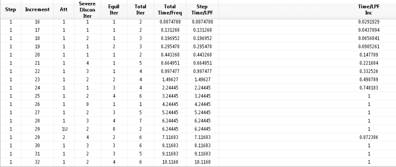
I am a bit confused About the interaction Parameter warning, since i never had it before. I post a screenshot regarding the increment size of the step. It uses an increment of size "1" and then it suddenly stops, shouldnt it usually try another iteration with a smaller increment size?

Monitor_prshnd.png
 
Try including this contact interaction between cracked faces as suggested by the first warning (in CAE use Edit Crack —> Specify contact property which is equivalent to *Enrichment, Interaction=... in input file). If this doesn’t help reduce initial and maximum increment size as well as increase the maximum number of increments (unless they are already correctly adjusted), use automatic stabilization in the step settings and damage stabilization in material properties. Also make sure that you checked Discontinuous analysis in solution controls. If your model is force controlled consider using displacement control instead.
 
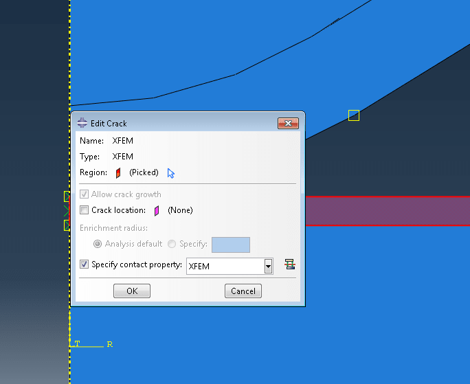
The convert severe discontinuities tab is checked and i added a automatic stabilization with the Default damping factor. I am still unsure though About the Enrichment error i got, i already added a contact property to the crack if that is what you meant, and i still got the error message:


XFEM_h0wj2o.png


And yes it is force controlled since the Rockwell test is a force controlled procedure. Does it make a big difference if i switch to displacement controlled and why?


Thanks for your help!
 
Displacement control is often advised for analyses involving severe nonlinearities (especially those caused by contact, buckling, crack propagation and so on). Usually it has great impact on convergence. In this case crack propagation can be unstable when using load control.

I was talking about different setting with similar name: „Discontinuous analysis” checkbox. It can be found in the same window where you change I_A - go to Step module, select Other —> General Solution Controls, pick your analysis step, check Specify and go to the first tab of Time Incrementation parameters group. There you will find this checkbox called „Discontinuous analysis”, right above parameters I_0 and I_R.

Do you have Nlgeom turned on ? If not it should be. Also make sure that material damage properties are correct.
 
Hey,

Thanks for your answers so far.
I checked the box "discontinous Analysis". Also i refined the mesh near the crack. NLgeom is on as well, unfotunately my simulation still aborts. I think i should try the approach via displacement control.

Also the error Please check to make sure that the interaction parameter is used on the *enrichment option for lefm criterion or low cycle fatigue analysis.
still occurs after implementing the contact property in the XFEM crack.
 
Since you don’t use LEFM-based damage criterion or LCF analysis (both require *Fracture Criterion keyword), I think that this warning is irrelevant in your case.

If none of the previously mentioned approaches helps with nonconvergence in this analysis then displacement control might be the only option left apart from changing your model’s assumptions.
 
Status
Not open for further replies.

Part and Inventory Search

Sponsor