Thank you in advance for taking to time to read through my questions. How do you define your allowable stress for a finite element analysis with a joint efficiency of 0.7?
Code: ASME Sec VIII Div. 1 2010 (No ed) with guidance from Div. 2 for FEA
Customer specific seismic requirement with reference to ANSI 360-05 and N690
I have completed my code calculations using COMPRESS however, due to our customers specific seismic requirements we are also analyzing the vessel and it's supports with FEA. I am familiar with the different levels of stress classification (general membrane, general membrane + bending, etc.) however, in the past when I have done this type of analysis the design was for a joint efficiency of 1. This time the design does not require any radiography therefore my joint efficient is 0.7. I believe a conservative approach would be to just take my allowable and multiply it by my joint efficiency but is this common practice for FEA?
Here is my specific example.
General membrane allowable limit: 20 ksi * 0.7= 14 ksi
Local and general membrane plus bending limit: 30 ksi * 0.7 = 21 ksi
general membrane + secondary stress limit: 60 ksi * 0.7 = 42 ksi
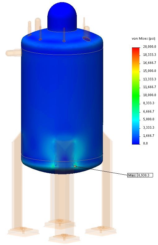
Below is a stress plot of the membrane stress. I realize in this example I am well below my allowable limit even after multiplying by a joint efficiency of 0.7 but that is not always the case. lets say the localize stress around the support is greater than 21 ksi. Because the stress crosses the circumferential seam it makes sense to me that the design would be unacceptable. However, say my deign uses support lugs and the localized stress area does not cross over a circumferential or longitudinal seam, would it still fall under the same allowable limit of 21 ksi or would the limit be 30 ksi?

