Continue to Site

Eng-Tips is the largest engineering community on the Internet

Intelligent Work Forums for Engineering Professionals

  • Congratulations KootK on being selected by the Eng-Tips community for having the most helpful posts in the forums last week. Way to Go!

Joint FEA Stress 1

Status
Not open for further replies.

Lee.Conti

Automotive
Nov 8, 2019
87
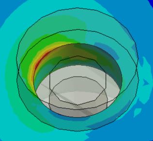
Capture_w6uoa7.jpg


Under static condition, the bolt hole stress shows some stress above yield, localized, the stress near the bolt head is below yield...

Should we use tensile strength instead of yield to do margin of safety check? I see the area underneath bolt head may experience little yield under bolt pretension.

Thank you!
 
Replies continue below

Recommended for you

First - to get a good answer from the forum you will need to provide more details of the problem you're analysing. Give an overview of the problem that you're trying to solve with this FEM. Is this a shear joint? is there significant out of plane load ? How is the fastener idealised?
Please draw a free body diagram.

Second - the results adjacent the fastener hole will be very sensitive to how this has been modelled.
Normally I would not work with model stresses at fastener holes. Rather I would extract loads from the fastener, then hand calculate stresses and margins as required .


agree with above, don't use this stress for anything. is the model with NL material ? if not, then the stress is not real.

this type of stress peak has been with us since the first hole was drilled. This is localised plasticity that does not affect the structural integrity of the structure.

This is why we have bearing stress allowables and fastener load allowables (so we don't need to burrow down into the weeds).

another day in paradise, or is paradise one day closer ?
 
Agree. Ignore all the stresses at the hole; they are incorrect. Better yet, DO NOT model fastener holes.
 
SWComposites said:
Better yet, DO NOT model fastener holes

But that would make the model simpler and faster. You're putting an army of FEA jocks out of work!
 
Thanks Ng2020, rb1957 (always :) )

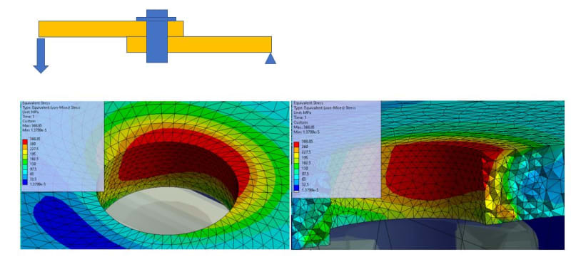
It is similar to lap joint under bending condition. after model washer into FEM, I see the stress even higher...

Was expecting some localized yielding and and the stress near bolt head is below yield... But it seems there are some red area with higher than UTS.

Will consider to use NL properties unless we are able to reduce the stress around the hole below UTS or only localized yielding.

Pic_ddlwoz.jpg


Note: Customer wants to see colorful result... So, I show stress plot... :p
 
You're putting an army of FEA jocks out of work! > Good. All they do is generate a pile of useless misleading random numbers.
 
Leeconti, If I understand your diagram it's a cantilever beam (I assume that's a fixed support on the right hand side) with a pin joint oriented vertically at the midspan.
Have a look in the USAF stress manual, from memory the section on lug analysis includes a closed-form method for analysing a beam in a socket which is somewhat similar to the scenario you're showing here. In short, the moment on the pin results in a triangular bearing stress distribution through the thickness of the lugs.
You could perhaps validate your FE analysis against the USAF closed-form solution.
 
regarding your cantilevered beam model ... what a terrible thing to do to a fastener ! I appreciate there are times when we all have to do terrible things in our designs (most often because we're put in a corner by others and told "figure it out".

If this is "truly" what you're modelling, model the contact between the plates, the preload, and NL material.

By all means show the customer the pretty pictures (they're some of our best "work") but it's difficult to relate to reality.
ultimate load ? ... apply a factored load ... stress results still "good" (NL material < ftu), then factor is your MS (conservatively)
limit load ? ... you are allowed limited "not significant" yielding at limit (as opposed to the usual trope "no yielding at limit" ... once you're looking at this detail, there'll always be some yielding at limit).
fatigue ... could be an issue ...

another day in paradise, or is paradise one day closer ?
 
A couple things to note...

This seems to be largely a repeat of many of the same things discussed in the following thread: thread2-480875

I fully agree with many of the comments above regarding fictitious stress artifacts sometimes resulting from FEM (as I noted in the other thread). However, I will also note the same caveat I did there.

Before "writing off" those peak stresses as non-problematic, it is pretty important to try to understand why they are appearing in the first place. How exactly are your joints modeled in the FEM (are the peak stresses the result from RBE "attachment points" or something else model related? Or is there something going on with the way you've loaded the model or constrained it?

Based on your description and FBD above - "It is similar to a lap joint under bending condition"... first off, I'm having trouble thinking of where that would be actually implemented as a design decision. But, that is a situation where you could very well in fact have a lot of eccentricity. Because of the rotation of the plates and the way the fastener impinges on the hole inner surface, you will have a highly skewed effective bearing area. This will cause the bearing load to be distributed over a much smaller area, and you could actually see pretty high stresses there.

Last, I will also note, that once you start running a non-linear analysis, writing margins becomes less about Ftu and more about strain. Remember, Ftu is usually higher than the rupture stress for ductile materials. So if you are running this non-linearly, where the stress will locally redistribute once it passes Fty, you actually want to write a strain margin. You should check that the strain at your ultimate load is less than the rupture strain. You should also be checking the scale of the plastically deformed material to make sure it is reasonable, and probably also check the maximum displacement as well.

Keep em' Flying
//Fight Corrosion!
 
Status
Not open for further replies.

Part and Inventory Search

Sponsor