Continue to Site

Eng-Tips is the largest engineering community on the Internet

Intelligent Work Forums for Engineering Professionals

  • Congratulations waross on being selected by the Eng-Tips community for having the most helpful posts in the forums last week. Way to Go!

Joint Pitch for Machining Part

Status
Not open for further replies.

sarclee

Mechanical
Jan 14, 2022
105
Hi, if the frame thickness is 0.75 - 1.00 D, is 4-6D pitch for rivet Shear joint still applicable?

The frame thickness is around 4mm thickness...
 
Replies continue below

Recommended for you

shear pitch is whatever it needs to be.

rules of thumb, depending on company, are 4-6D, 6-8D, etc. but these are rules of thumb. 10D is not (in and of itself) "unacceptable".

With shorter pitches net section becomes a concern. With longer pitches, inter-rivet buckling and possibly shear buckling.

One thing to watch ... the frame flange thickness and the skin thickness should be "similar" or thicker. You don't want a heavy (thick) skin on a light (thin) frame.

"Hoffen wir mal, dass alles gut geht !"
General Paulus, Nov 1942, outside Stalingrad after the launch of Operation Uranus.
 
It all depends on the loads. You need to do a proper, detailed stress analysis.
 
Thanks rb1957 & SWComposites. I start with basic pitching and then do the calculation from the nodal forces.

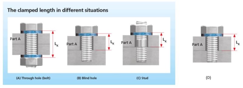
We have some product using through hole but not bolt and nut joint (#D). I would like to know if there is a standard to determine the thickness of Part A, the material being fastened?

Based on Nord-Lock, clamp length at least 3 times. Does it mean we have to use washer to compensate the clamp length if Part A is too thin?

Capture_crtg5j.jpg
 
Wow... I thought I knew fastening... But this one has stumped-the-chump.

I simply have no idea what the real questions/issue is from the OP.

Regards, Wil Taylor
o Trust - But Verify!
o We believe to be true what we prefer to be true. [Unknown]
o For those who believe, no proof is required; for those who cannot believe, no proof is possible. [variation,Stuart Chase]
o Unfortunately, in science what You 'believe' is irrelevant. ["Orion", Homebuiltairplanes.com forum]
 
I think "Lk" as shown only influences the stretch of the bolt ... not the strength of the installation.

I would ask Nord-Lock help desk. Are they giving you "turn of nut" or bolt stretch requirements for torque setting ??

"Hoffen wir mal, dass alles gut geht !"
General Paulus, Nov 1942, outside Stalingrad after the launch of Operation Uranus.
 
I guess, your question is very valid in case there is a separation force between Part A and Part B (lover plate). You may be worrying about punching shear, adding washer will increase shear cross section and will be helpful. If the concern is shear (lateral) I think you need to check bearing and tearing on the thinnest plate in the connection as well as shear on the bolt.

Therefore the loading type is essential part of the discussion. You cannot get proper answer if you do not provide it in your post unfortunately. Perhaps a hand sketch might be helpful. Perhaps you will find your answer during the load sketching, you never know.
 
I have seen not only Nord-Lock suggesting the clamp length is 3 times of the bolt diameter. If the joint I use is (D), does it mean I have to use 3x dia for part A thickness? It seems too thick as I have seen this joint, like the picture below, in our product with thinner part A...


Screenshot_2022-08-24_215039_wtc2d9.png


OK, still confused.. BUT... for the examples shown above... cover or Assy fastened to a body with cap-bolts [mostly-threaded, heavy-duty screws] in tension...

The cap-bolts generate TENSION force ONLY. IF substantial SHEAR forces are present, then the joint must also have a way to remain fixed/stable to resist shear. This is typically accomplished with precision-fit [net-fit] SHEAR-PINS between the parts and positioned/spaced strategically within the fastener pattern.

NOTE1. Shear-pins I am referring-to are headless... such as solid dowel-pins machined to x.xxxx-inch tolerances... or coiled-spring pins for less precision assys... and are typically made from high strength steel or SStl with tapered-ends to facilitate a tight-fit installation into precision-matched holes between assemblies. They can also be used for guide/alignment between critical mechanical assemblies... as well as shear-force resisting.

Regards, Wil Taylor
o Trust - But Verify!
o We believe to be true what we prefer to be true. [Unknown]
o For those who believe, no proof is required; for those who cannot believe, no proof is possible. [variation,Stuart Chase]
o Unfortunately, in science what You 'believe' is irrelevant. ["Orion", Homebuiltairplanes.com forum]
 
L/D of 3 is typical design "rule of thumb". Your sketch (from Linkedin) is IMHO misleading (or not helpful in your situation, shown in your post of 22nd).

I don't know of a limitation of the thickness of the clamped plate, Lk in d), other than bearing etc.

"Hoffen wir mal, dass alles gut geht !"
General Paulus, Nov 1942, outside Stalingrad after the launch of Operation Uranus.
 
Does the pitching affect fastener pull out strength?

There is no input of the plate width needed in the calculation... Does it mean pitch is only driven by Shear load?
 
In your joint config D from 22 August, the thickness of part A has nothing to do with the pull out strength of the threaded part.

I have no idea what shear load you are referring to. Pull out strength is related to an axial load on the fastener.
 
"tension" pull out or "shear" pull out ?

"Hoffen wir mal, dass alles gut geht !"
General Paulus, Nov 1942, outside Stalingrad after the launch of Operation Uranus.
 
Status
Not open for further replies.

Part and Inventory Search

Sponsor