Continue to Site

Eng-Tips is the largest engineering community on the Internet

Intelligent Work Forums for Engineering Professionals

  • Congratulations KootK on being selected by the Eng-Tips community for having the most helpful posts in the forums last week. Way to Go!

Joist Span Dimensions Question

IanVG

Mechanical
Jan 21, 2022
73
Hello all! Another question from a ME with little experience in structural engineering. For drawings from the early 1970's in the southeastern U.S., how were concrete joist spans dimensioned? I can figure the span length from the distance from beam to beam, but from the top to the bottom of the joist sections, there is not a single dimension on the entire set. Is this intentional? How do I know how many joists there are in a given joist span? I can eyeball it, but I suspect that's not the intention here.

Thanks in advance!
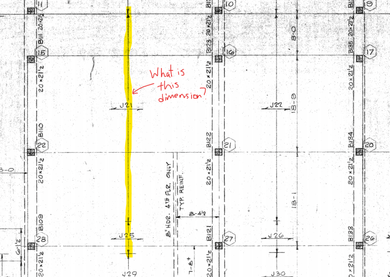
Screenshot_2024-10-02_173628_m4b8qi.png
 
Replies continue below

Recommended for you

I doubt J21 is any kind of standard designation.

FaQ has a link to an older CRSI that would give you more of a background on concrete pan joists.
 
Look for a joist schedule. It should tell you all you want to know about Joist J21, J22, J25, etc.
 
Hey phamENG, thanks for the reply. The joist schedule only tells me the following: pan depth, slab depth, and the width the joist @ spacing dimension. For example an 18" thick joist below a 3-1/2" slab, with a 7" width @ 37" off center. The .pdf I attached to the previous reply shows pretty much everything I can see. I'm still not seeing anything on any schedule or typical detail that explains how to size the number of joists. Was that left up to the contractor back in the day? Looking through the CRSI manual, tells me how to size the span, not how to read the drawing that I have. I guess I could work backwards through the tables, but I was under the impression that the drawings would describe everything I needed to know in order to the model the building.
 
 https://files.engineering.com/getfile.aspx?folder=f511f021-46c7-4b67-9e23-a9e8eb78113a&file=196X-S3.pdf
The CRSI should have the more typical spacing for the joists, I'd say 30" spacing is fairly typical but that should be on the schedule. This sounds like something you need a local structural engineer on.

If you need to cut holes for mechanical stay in the flat portion to save the structural engineer a headache.
 
lexpatrie, the spacing is on the schedule at 37" center to center of each joist. I'm recreating part of the building in Revit, and I wanted to model the space more accurately. The joist spacing is given, but the dimension I highlighted in the first picture is not given. Does my question make sense? I am not trying to cut any holes, I just wanted to run through this exercise to better understand structural drawings and how to apply them.
 
there must be some feature on the full drawing (outside the screen shot area) that defines the ends of the J21 and J25 joists (the dimensions shown in yellow).
 
SWComposites, that's what I would expect, but I found nothing. I think the answer is that the contractors back in the day were expected to perform some of the locating of the joists themselves on-site. I am attaching the full structural set of drawings to this reply so one can see for themselves. Link to drawing download.

I was hoping through this post, to get more insight on how to generally model structural elements for older building. It seems that the only way to get accurate dimensions on the joist number and offsets are to go on-site and measure. Except for building with exposed structures, this is pretty difficult. So I'll just have to get more accurate only where it is critical.
 
I've added a related, but separate question at this thread (thread507-523177), about how the first pan spacing is confirmed.
 
I think the first dimension is usually shown on the plan somewhere? I haven't looked at a pan joist design drawing in about 15 years. Look at that CRSI that might give you an idea of something more typical, a lot of engineers don't really follow that guidance specifically but you can at least poke around.
 
I agree with lexpatrie, often at one end or the other there will be a "start joist layout here" note or a dimension to the first joist, then you just work your way across the building from there. The pan forms were fairly typical so once the first joist is located, the rest just end up where they end up using the pan forms.
 
lexpatrie and jayrod12, thank you so much. Great insight! It's good to hear from engineers about what should be done. I could be missing something, but the first dimension was not called out anywhere. I learned that what I've meant to say earlier, is asking about the edge rib. I was mistaken in thinking that the edge span and the interior span were the correct terms. The edge span is the joist system that borders no joist system on one side and potentially a joist system on the other (e.g. a joist system next to an exterior wall). An interior span is a system of joists that is bordered by a joist system on either side. I have a copy of the 1980 CRSI design handbook, and I couldn't find anything in the concrete joist construction chapter except lots of tables for designing spans (end and interior). There might be something else in the handbook that would help me, but I cannot find it.

I'm assuming that maybe for this age of construction, the contractor worked out exact plans of where the joists would go and confirm that the rib and header locations (which are not dimensioned exactly by the engineer) would satisfy the engineer of record. I still don't understand why there were the same joists in parallel, there's no note to 'start joist layout here,' it's just the same layout through in parallel. In the field I have confirmed that there are occasionally double joists and the such, but they don't match too well with the drawings.
 
The pan forms were at least somewhat standardized, so that's perhaps part of it, as in you're looking for the depth of a W8x15 which has known values, for example.

What I think varied was mostly the web width and the reinforcing in the joist. The thinner flat portion was a standard width, so it's similar to T heam construction at least partly and there were provisions for pan joists (specific to shear, as I recall) in the older codes (ACI 318) that may still exist.

I don't specialize in these. They are archaic and the people with direct design experience are quite far into their careers if not retired. My knowledge comes from say one or two load evaluation projects circa 2001 and engineers 20 years ahead of me.

I'd expect many of these are were designed "off the shelf" via CRSI tables.

They are kind of analogous to open web steel joists, with span tables, etc. But OWSJ are still predominant, for roofs particularly.
 

Part and Inventory Search

Sponsor