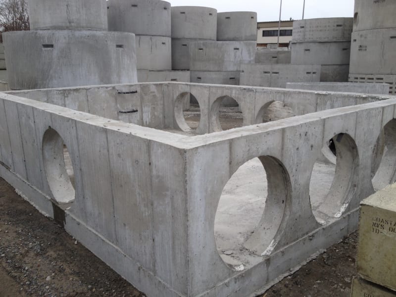
I did a bunch of quite large junction chambers a few years ago, so the design process is still relatively fresh in my mind. I basically designed it twice: once as if it were a concrete water tank above ground, and once as a buried, traffic bearing tunnel.
1) Made separate RISA models of each wall and slab, with large openings modelled.
a) Fixed boundary model to maximize negative moments
b) Pinned model to maximize positive moments
c) Apply soil and hydro pressure loads for walls; uniform gravity pressure loads and concentrated "patch" loads for HS-20 truck wheels the roof; reaction pressures for the base slab.
d) My project was in Missouri with relatively high seismic, and was critical infrastructure so I did seismic soil pressures, sloshing and vertical seismic loads
2) Hand calcs to design reinforcement based on peak moments and shears from RISA model.
a) Since walls are modelled individually in 2D, remember to include the out-of-plane reactions from orthogonal walls as added in-plane tension for sizing reinforcement. This would apply for a load case with net wall pressure acting outward, say if there is a leak test before backfill. Similarly remember to apply roof slab reactions as axial line loads for wall design.
b) Design per ACI 350.
3) Hand calcs to check global stability under buoyancy for every possible condition. Worst case is likely empty chamber before backfill and before roof, in a flooded hole. You can take advantage of the wall holes here to limit the buoyant water elevation (assuming the holes are formed in place and not to be cut out later).

![[pipe] [pipe] [pipe]](/data/assets/smilies/pipe.gif)
![[lol] [lol] [lol]](/data/assets/smilies/lol.gif)
