Continue to Site

Eng-Tips is the largest engineering community on the Internet

Intelligent Work Forums for Engineering Professionals

  • Congratulations KootK on being selected by the Eng-Tips community for having the most helpful posts in the forums last week. Way to Go!

Junction Boxes

Status
Not open for further replies.

ATHS

Structural
Jan 14, 2022
20
Hello everyone,

This is my first time posting here.

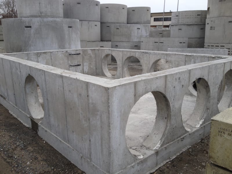
I need to design a junction box (see attached). Have received conflicting inputs from other sources on the design approach. Anybody here ever worked on something similar? I would like to get a brief design approach.

Thanks
 
 https://files.engineering.com/getfile.aspx?folder=3a0da3ab-755d-472c-a380-226274e74c2f&file=Capture.pdf
Replies continue below

Recommended for you

We would call that a stormwater pit in my country. Our approach has been to create a 3d grid model for complex pits
 
I did a bunch of these a few years ago for a design build project. They were shallow drainage structures with large pipes; everything was precast.

The top slab was designed as a bridge deck with reinforcement perpendicular or parallel to traffic depending on the situation. The walls over the pipe penetrations were designed as simply supported or continuous beams carrying the top slab. The walls between the pipes were treated as columns for the top slab loads and cantilever beams for the lateral loads. Bottom slab was designed as a one way slab.
 
Pretty much the way I would approach it, except the walls would be treated as flexural items, too. I wouldn't rely on the pipes to provide lateral restraint.[pipe]

Rather than think climate change and the corona virus as science, think of it as the wrath of God. Feel any better?

-Dik
 
I did a bunch of quite large junction chambers a few years ago, so the design process is still relatively fresh in my mind. I basically designed it twice: once as if it were a concrete water tank above ground, and once as a buried, traffic bearing tunnel.

1) Made separate RISA models of each wall and slab, with large openings modelled.

a) Fixed boundary model to maximize negative moments​
b) Pinned model to maximize positive moments​
c) Apply soil and hydro pressure loads for walls; uniform gravity pressure loads and concentrated "patch" loads for HS-20 truck wheels the roof; reaction pressures for the base slab.​
d) My project was in Missouri with relatively high seismic, and was critical infrastructure so I did seismic soil pressures, sloshing and vertical seismic loads​

2) Hand calcs to design reinforcement based on peak moments and shears from RISA model.

a) Since walls are modelled individually in 2D, remember to include the out-of-plane reactions from orthogonal walls as added in-plane tension for sizing reinforcement. This would apply for a load case with net wall pressure acting outward, say if there is a leak test before backfill. Similarly remember to apply roof slab reactions as axial line loads for wall design.​
b) Design per ACI 350.​

3) Hand calcs to check global stability under buoyancy for every possible condition. Worst case is likely empty chamber before backfill and before roof, in a flooded hole. You can take advantage of the wall holes here to limit the buoyant water elevation (assuming the holes are formed in place and not to be cut out later).
 
Thank you for the response,

What direction would my span be? The traffic is parallel to 44" and 42" dia pipes. The top slab is supported in all four direction. If I take my span to be 22.5 ft, It's going to require high reinforcement which isn't consistent with other similar drawings I have seen.
 
I would design this as a 1-way top slab, so your clear span is 6ft.

Do you have a traffic load above?

How much fill will be on top of the top slab?

Before you do any design, you can figure out some preliminary geometry. Your junction box is basically a 6ft span box culvert with holes in the sides.

Go to the TxDOT or FDOT websites and look at their cast in place box culvert standards. TxDOT has them sorted by the amount of fill on top. You can get preliminary geometry there, and then do analysis.


Also, this is up to you, but I always set the bottom slab 6" (+pipe thickness) below the lowest pipe and then have them grout the floor back up to the final elevation. That way the contractor has a little wiggle room to make sure the junction box drains. They can also grout smooth regions in the corners to reduce the chance of sediment build-up.
 
@JoelTXCive Why do you say the span is 6ft?, because of the traffic direction ?
To answer other questions yes, there is traffic on top of culvert. I don't have much cover to play with ( 6" to 1').
 
Bones... I've never designed them for wind loads...[lol]

Rather than think climate change and the corona virus as science, think of it as the wrath of God. Feel any better?

-Dik
 

With a 2 way slab, the span is 'always' the short dimension. If you take a look at design coefficients for an aspect ratio in excess of 3 for simply supported slab, the short span moment is much greater than the long span moment. The short span moment would be nearly ql^2/8. The slab stiffness in the short direction is so much greater than that in the long direction.

Rather than think climate change and the corona virus as science, think of it as the wrath of God. Feel any better?

-Dik
 
AHS - I would use 6' as the span and design it as a slab with reinforcement parallel to traffic per AASHTO.

dik - For the wall between the pipes, I didn't assume any lateral restrain from the pipes. This is a picture of one of the largest boxes.


S15_2_xvel3g.jpg
 
Status
Not open for further replies.

Part and Inventory Search

Sponsor