Continue to Site

Eng-Tips is the largest engineering community on the Internet

Intelligent Work Forums for Engineering Professionals

  • Congratulations pierreick on being selected by the Eng-Tips community for having the most helpful posts in the forums last week. Way to Go!

K (effective length factor) influence on Mr for cantilevered beams 1

Status
Not open for further replies.

EngDM

Structural
Aug 10, 2021
598
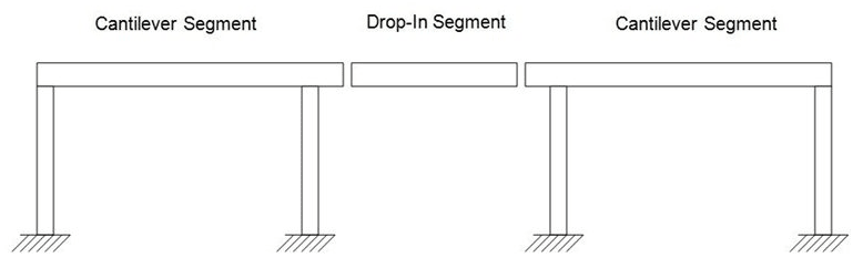
I found a document listing different K values for various laterally restrained conditions for Gerber-Girder cantilever beams. From what I can see in the CSA S16:19 the equations for moment resistance do not depend on K, and the beam selectiont ables do not show "effective unbraced length" similar to how it is presented for the compression member tables.

I've seen others take the moment capacity based on twice the unbraced length of the cantilever, but I can't find anything that shows or explains how K influences the bending strength of the beam.

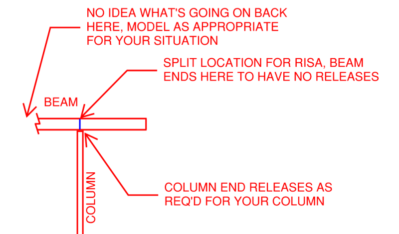
Do any of you have a reference or further insight to these systems? Even changing K in Risa doesn't change the Mr of the beam.
 
Replies continue below

Recommended for you

Steel Interchange, March 2005 Design of Cantilever Beams

RISA probably isn't set up to "catch" this behaviour, or you need to make a series of adjustments to the beam design criteria, but K wouldn't be the route, that's why your Mr isn't changing. In terms of terminology, you need Mcr here, not Mr. Mcr being the buckling value. Mr being the inelastic flexural yielding value.

This tends to come up quite a bit, but responses since 2005 are a lot less visual.

[link ]AISC Steel Interchange Index[/url]

One of the later replies from AISC points at the Guide to Stability Design Criteria for Metal Structures, Galambos editor.

Steel Design After College is another good reference for some coverage of this topic, as it gets into the guts of Cb to some degree.

Regards,
Brian

Edit - the way to deal with it inside RISA might be to change the Lb value.

Modern Steel Construction, July 2004, Unbraced Length of Cantilever
 
Yes, this is currently a gap in AISC (and I imagine in CSA S16) based on two precluding conditions -- AISC assumes torsional restraint at supports, and typical building detailing would not result in cantilever beams with unbraced lengths long enough that they would torsionally buckle. When those assumptions aren't appropriate, the effective length of a cantilever and the critical buckling stress/capacity is often in the range corresponding to 1.5-2.5x the physical length, and sometimes as high as 7.5x!

There doesn't seem to be consensus, but I tend to use the same references as Lexpatrie when applicable.
 
lexpatrie said:
In terms of terminology, you need Mcr here, not Mr. Mcr being the buckling value. Mr being the inelastic flexural yielding value.

Interestingly enough, in the CSA S16 code Mcr (or Mu in this book) gives the same equation as the 2005 article you've linked, but without any K values in front of L. I am curious as to why they are doing this.

It looks like Risa does not use K in it's Mcr (Mu) equation. Further, RISA calculates and applies the Cb (w2 in CSA), when according to the 2005 article it should be 1 for cantilever sections.

Is this 2005 article ever reiterated anywhere within the Steel Construction Manual? It appears that I'll be defaulting to that manual until the Canadian book provides more.

Lomarandil said:
Yes, this is currently a gap in AISC (and I imagine in CSA S16) based on two precluding conditions -- AISC assumes torsional restraint at supports, and typical building detailing would not result in cantilever beams with unbraced lengths long enough that they would torsionally buckle. When those assumptions aren't appropriate, the effective length of a cantilever and the critical buckling stress/capacity is often in the range corresponding to 1.5-2.5x the physical length, and sometimes as high as 7.5x!

My case is just a beam line with cantilevers and drop in sections to reduce overall section size. I'll have supports at 5' from my joist top chords, but I'm trying to figure out if I need bottom flange bracing or not; I need the appropriate way to calcualte Mr at the cantilever assuming top flange support only.

Is taking my length as K*cantilever and a Cb of 1.0 adequate and not overly conservative?
 
Even now, it's not in the AISC manual (AISC calls for Lb=L and Cb=1.0, based on those assumptions I mentioned). I believe it's codified in the current UK steel codes, but the Guide to Stability Design Criteria (5th Ed) is as official as it has become in US practice.
 
AS other have said if you manually modify the effective length as appropriate then you should be good. This is the reference I use. I believe it is essentially the same as Lexpatries reference though possibly slightly easier.


It isn't uncommon for me to design reasonably significant steel cantilevers gantries (6-7m). So an effective length of >50m if I don't restrain things suitably!

I generally use stiffeners and a deep channel or fly braces to provide torsional restraint. Lateral restraint is generally provided by my lateral restrain system which is just in plan bracing.
 
No, whether a load is normal or destabilizing (or stabilizing) is in reference to the load application height relative to the height of the support.

I don't know off the top of my head how BS differentiates normal and destabilizing loads.

In my niche of construction engineer, a suspended beam is often a stabilizing load case, where the load is applied below the point of support, and therefore any lateral movement and buckling would tend to self-correct. In the US, Helwig has performed some research and offers some Cb factors which can be used to take advantage of this when predicting LTB capacity.
 
If you're doing Gerber Girders they shouldn't have all that much of a cantilever, compared to the main spans. Read Rongoe, that's your guy and your code (CISC).

Roof Framing with Cantilever (Gerber) Girders and Open-Web Steel Joists - Rongoe, CISC, 1989.

Depending on how you connect the main beam to the drop-in beam, you may get rotational restraint there, and the top flange, recognized as where you want the brace, tends to be braced by the metal deck.

BRUH! This document is suddenly FREE to everyone?

Hemstad, Michael (1999). "Cantilever Beam Framing Systems," Engineering Journal, American Institute of Steel Construction, Vol. 36, pp. 129-137

OH HAPPY DAY!

Regards,
Brian


lexpatrie said:
Edit - the way to deal with it inside RISA might be to change the Lb value.

The only issue with this, is I like to use the SEGMENT function. This way it checks my negative bending between nodes. The only issue with this, is it doesn't amplify the cantilever Lb, or take Cb as equal to 1 for the cantilever end. In changing the Lb, I would need to save a model to check my negative bending between supports, and another file with the Lb increased to k*Cant_length.
 
EngDM,

If you're using SEGEMENT, then just go ahead and physically break the member at the last node before the cantilever. Now you can futz directly with the design properties of the cantilever portion, and still have the rest of the beam get the benefit of the automatic Cb calculation. Just make sure that the new beam ends are transmitting moment, and not moment released.

Please note that is a "v" (as in Violin) not a "y".
 
I'll add the following:

From the AISC perspective, and I believe I read this in one of the above referenced Steel Interchange articles, the effective length is twice the cantilever (i.e. free cantilever like a flagpole, K=2 for axial buckling), in terms of Lb, but the Cb is 2.0 "analytically" (perhaps incorrectly, but it's what calculates out), so the specification has you use the actual length and Cb = 1.0 which produces the same results. If anybody knows formally where that information came from, feel free to add for the OP's benefit (and I suppose mine as well, if nobody else).

In terms of RISA, I thought you could force Cb = 1.0 in the parameters somewhere, that should produce the necessary results. I use RISA very rarely. It's likely to actively don't want RISA to calculate a Cb for the cantilever.

 
lexpatrie said:
so the specification has you use the actual length and Cb = 1.0 which produces the same results

In the publication above it says to use Cb = 1.0 and use the appropriate K. Cb does not occur under the square root so they aren't quite equivalent. Some of the Kc's are much larger than 2.0, so ignoring the analytical Cb = 2.0 and setting it to 1.0 can still be incorrect.
 
WinelandV said:
If you're using SEGEMENT, then just go ahead and physically break the member at the last node before the cantilever.

The splice end should be pinned and over the column should be fixed correct? Does doing this not introduce shear deformation and give inaccurate deflection assumptions? I read on here before that RISA calculates shear deformations at member end and start nodes.
 
So, back when I used to do technical support for RISA, we'd get a number of questions about the Canadian code check.

That was more than 6 years ago now (incredibly how time flies!), so my knowledge may not be up to date. However, if I remember correctly (which is a big IF), RISA doesn't really know if a beam is a cantilever or not. There isn't a flag in the program for this.

Now, that may not be 100% true anymore. If the RISA model came over from RISAFloor (or even Revit Structure) then there is likely a flag where the program knows that a beam is a cantilever or not. But, I don't believe the program uses this in any of it's code check calculations.

 
EngDM,

This is my understanding of what you're doing - running a beam over the column that in reality will be continuous, but in RISA you split it there so that whatever's going on with the beam on the non-cantilever side of the column isn't affected by the design parameters you need for the cantilever portion:

Cantilever_twzpd8.png


My apologies if I have misunderstood your situation.

Please note that is a "v" (as in Violin) not a "y".
 
WinelandV said:
This is my understanding of what you're doing - running a beam over the column that in reality will be continuous

Pretty close to your sketch, except with a spliced beam on the RHS. For the connection to the spliced beam, I imagine I'd use a pin support? Your diagram above says ends, plural, to have no releases.
 
Can you post a sketch?

Please note that is a "v" (as in Violin) not a "y".
 
I'm talking AISC, the K stuff you're talking about is CISC, if I'm not missing something. I suppose you're using the Canadian design codes where it's more involved.

If you're really doing cantilever suspended span, you'd include the other drop-in beam. That would be pin connected to the "free" end of the cantilever.
 
Status
Not open for further replies.

Part and Inventory Search

Sponsor