Hi everybody,
this is my first time here, I hope you can advise me.
months ago we had a problem in one generator coupled to a main engine, the engine was tested and generator not online, so we had high voltage alarm, nominal is 690V and went to 900V, on the DECS 200 I got LOSS OF SENSING VOLTAGE, we opened the generator and found the SENSING TRANSFORMER (690V/110V) and the DAMPING RESISTOR burned, so we received new ones, not the same but the same characteristics, when installed the new things we tested and we got only 655V, so we tested the transformer on workshop and if we apply 690V on the primary we get 116V on the secondary, so we decided to increase the setting on the DECS 200 on the section..
SYSTEM PARAMETERS/TRANSFORMERS.....GEN PT SEC = 110V ...we changed to 116V
So we tested and now we get 690V and KVar is positive, when put in parallel with another generator the KVar is negative but we do not get any alarm, when we put three generators online KVar is more negative and we get alarm on the IAS(REACTIVE LOAD SHARING ERROR on the computer in control room) the other two generator Kvar is normal. When we put four on line we do not get any alarm and KVar is positive but way less than the other three generators.
We got in contact with hyundai and recommended to change this parameter
SYSTEM PARAMETERS/TRANSFORMERS.....GEN PT PRI = 690V ....TO 655V (volts we get with the new transformer) and
SYSTEM PARAMETERS/TRANSFORMERS.....GEN PT SEC = 110 (keep it in 110V)
We tested and we got the same results....
do you think that this problem could be caused by the ratio of the SENSING TRANSFORMER?
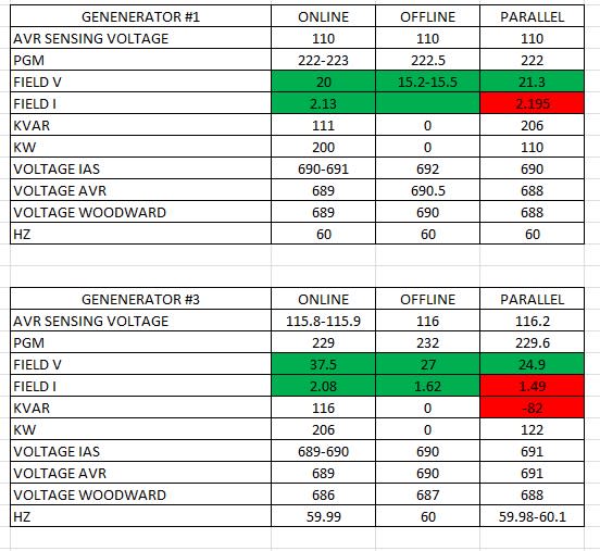
here it is a table of parameters we meassure with two generators...GENERATOR 3 is the one with the problem.

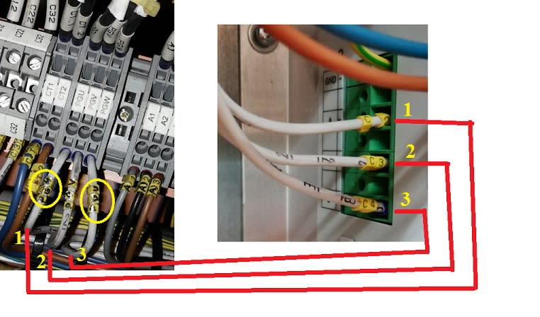
Another thing that is making me noise...when megging, and inspecting the generator, diodes, etc, I disconnected some cables that goes to the DECS 200, when connecting again I notice one thing...that the cables PGU, PGV, PGW that goes to the DECS 200 were "interchaged PGU and PGW" and I put "interchaged" because I am pretty sure that they cannot swap. Anyway before testing I look in the numbers printed on the cables and 1, 2, 3 correspond to the same position in the AVR and the PGU, PGV, PGW according to the diagram....I think the person that put the labels was wrong...here it is a picture to explain better....
in diagram
PGU go to C2
PGV go to C3
PGW go to C4
that is why I paid attention to the number printed on the label not the yellow labels that I think they are wrong.
Anyway...what could happen if PGU and PGW are swap?

I hope you can help me guys...
thank you
J.G.
this is my first time here, I hope you can advise me.
months ago we had a problem in one generator coupled to a main engine, the engine was tested and generator not online, so we had high voltage alarm, nominal is 690V and went to 900V, on the DECS 200 I got LOSS OF SENSING VOLTAGE, we opened the generator and found the SENSING TRANSFORMER (690V/110V) and the DAMPING RESISTOR burned, so we received new ones, not the same but the same characteristics, when installed the new things we tested and we got only 655V, so we tested the transformer on workshop and if we apply 690V on the primary we get 116V on the secondary, so we decided to increase the setting on the DECS 200 on the section..
SYSTEM PARAMETERS/TRANSFORMERS.....GEN PT SEC = 110V ...we changed to 116V
So we tested and now we get 690V and KVar is positive, when put in parallel with another generator the KVar is negative but we do not get any alarm, when we put three generators online KVar is more negative and we get alarm on the IAS(REACTIVE LOAD SHARING ERROR on the computer in control room) the other two generator Kvar is normal. When we put four on line we do not get any alarm and KVar is positive but way less than the other three generators.
We got in contact with hyundai and recommended to change this parameter
SYSTEM PARAMETERS/TRANSFORMERS.....GEN PT PRI = 690V ....TO 655V (volts we get with the new transformer) and
SYSTEM PARAMETERS/TRANSFORMERS.....GEN PT SEC = 110 (keep it in 110V)
We tested and we got the same results....
do you think that this problem could be caused by the ratio of the SENSING TRANSFORMER?
here it is a table of parameters we meassure with two generators...GENERATOR 3 is the one with the problem.

Another thing that is making me noise...when megging, and inspecting the generator, diodes, etc, I disconnected some cables that goes to the DECS 200, when connecting again I notice one thing...that the cables PGU, PGV, PGW that goes to the DECS 200 were "interchaged PGU and PGW" and I put "interchaged" because I am pretty sure that they cannot swap. Anyway before testing I look in the numbers printed on the cables and 1, 2, 3 correspond to the same position in the AVR and the PGU, PGV, PGW according to the diagram....I think the person that put the labels was wrong...here it is a picture to explain better....
in diagram
PGU go to C2
PGV go to C3
PGW go to C4
that is why I paid attention to the number printed on the label not the yellow labels that I think they are wrong.
Anyway...what could happen if PGU and PGW are swap?

I hope you can help me guys...
thank you
J.G.
