Continue to Site

Eng-Tips is the largest engineering community on the Internet

Intelligent Work Forums for Engineering Professionals

  • Congratulations IDS on being selected by the Eng-Tips community for having the most helpful posts in the forums last week. Way to Go!

L-N PT's on a LRG system

Status
Not open for further replies.

rockman7892

Electrical
Apr 7, 2008
1,156
Is it permissible to have L-N PT's on a MV (12.47kV) LRG or HRG system? I'm looking at a project where there are several (1) 7.2kV:120V PT's that are suggested for replacement in converting system from solidly grounded to LRG. I'm assuming reason is that it is not permitted to have any L-N connection on an LRG system.

Assuming the same would apply for any station service transformers connected L-N on primary?

I'm assuming these single phase connections are L-N and not L-G? The drawings I've seen represent a ground symbol on the other side of PT primary but I take this to be neutral since current has to flow back to neutral of transformer and is not intended to flow on ground system?

There also appear to be some PT's that are a (3) PT configuration shown as 7.2kV:120V. I'm assuming this would be these PT's in a wye configuration? I don't think there is an issue with this wye connection on an LRG system however do these PT's not need to be rated for full L-L voltage instead of L-N voltage?
 
Replies continue below

Recommended for you

Does this help?

image_ts8sgm.png


Bill
--------------------
Ohm's law
Not just a good idea;
It's the LAW!
 
Re-visiting this one with some new information and wanted to get some input from others on the following:

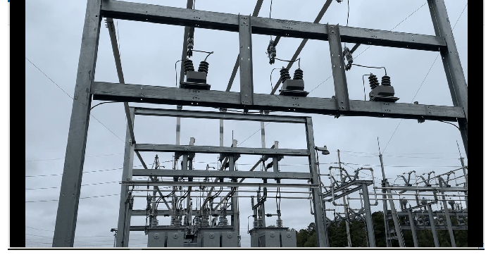
1) Existing PT's connected L-G are listed in BOM as 12kV potential transformer (7,200-120). Seeing that these are (2) bushing PT's would this indicate that these could be connected at L-L voltage but would have a different nominal secondary voltage

2) Its my understanding that a L-L rated PT can be used for a L-G connection however unless the PT ratio is changed the secondary voltage reading will be higher. So for instance if I want to connect L-L or keep L-G with elevated voltage rise during ground fault we need a 14400:240 PT as davidbeach points out or if we re-use existing PT's (assuming they are adequate) we'd have a 208V nominal secondary rating instead of 120V since we're re-using the 60:1 PT connected with different primary voltage.

3)Is there any issue with the impedance grounded system of having a nominal secondary of 120V and then having that secondary voltage rise to something larger than 120V under fault conditions if PT was adequately rated for L-L?

4) I'm a bit turned around on nomenclature for CPT that I'm looking at. If a CPT has designation of 7200/12470Y 120/240 does that mean that the primary winding is rated for only 7200V and can only be connected L-G (Not L-L)? To me the 7200 designates the L-L voltage rating and the 12470Y number derives that same 7200V so to me this is a 7200V PT. Perhaps I'm looking at it wrong?

5) Our particular application is considering using a grounding transformer in the form of a zig zag transformer with LRG connected to neutral. Is it typically to have CT on grounding transformer neutral with associated relay, or is it usually just a grounding transformer to provide ground fault source with ground fault current detected elsewhere (feeders, incoming transformers, etc...)

 
rockman7892-

To your questions:

"1) Existing PT's connected L-G are listed in BOM as 12kV potential transformer (7,200-120). Seeing that these are (2) bushing PT's would this indicate that these could be connected at L-L voltage but would have a different nominal secondary voltage"

No, you have to look at the nameplate. If the voltage rating is listed as 7200/12470Y (which I'm 99% sure that's what you have from your description and picture), that means that the VTs can be connected L-N on a 12470V system or line-to-line on a 7200V system. Either way, the rated primary voltage is 7200V. Under IEEE C57.13, these would be Group 1 VTs, which mean that they have an over-voltage factor (OVF) of 1.25 - 8 hours and 1.1 - continuous.

If you want a 2 bushing VT connected line-to-neutral with a 7200:120 (60:1) ratio, but you want the VT to withstand the neutral rising up to the system voltage, then the unit would need to have an OVF of 1.73 for some period. Commonly we se such units defined with an OVF 1.9 - 8 hours. Also, OVF 1.73 - 1 minute is a common rating.


Is this for metering or relaying? If you apply a L-L rated VT L-G, your metering accuracy may suffer.
 
scottf - Thanks for the explanation, that clears up some PT rating information that I wasn't clear on before.

I've decided to keep PT's in a wye configuration (L-G) as opposed to changing to open delta in order to keep all measured values that wye PT's provides. So based on this I now see that there are (2) options for PT ratings:

1) As scottf explains above you can connect a 7200V rated PT L-G if it is an IEEE Group 1 PT rated for an (OVF) of 1.1 or 1.25 (assume these would have 2 bushings instead of single bushing)

Or

2) Install a L-L rated PT such as a 13200/13200Y PT that is connected in a L-G configuration. The specific one I'm looking at has a 110:1 ratio so would provide 65.5V on secondary or 113.36 when setting secondary L-L value in relay.

Is there any issue with having relay see voltage shift during a L-G fault and thus report and display elevated phase voltage on relays until system clears fault current? In other words is there any disadvantage to sticking with the wye PT configuration as opposed to changing to open delta?
 
Status
Not open for further replies.

Part and Inventory Search

Sponsor