Continue to Site

Eng-Tips is the largest engineering community on the Internet

Intelligent Work Forums for Engineering Professionals

  • Congratulations KootK on being selected by the Eng-Tips community for having the most helpful posts in the forums last week. Way to Go!

L shape bracket 1

Status
Not open for further replies.

ynnuseel0106

Structural
May 14, 2015
10
If I have a L-shape bracket with bolts on each face anchored into the supporting R.C. structure subject to a moment and shear load, how can I determine whether the bolts will take tension or shear?
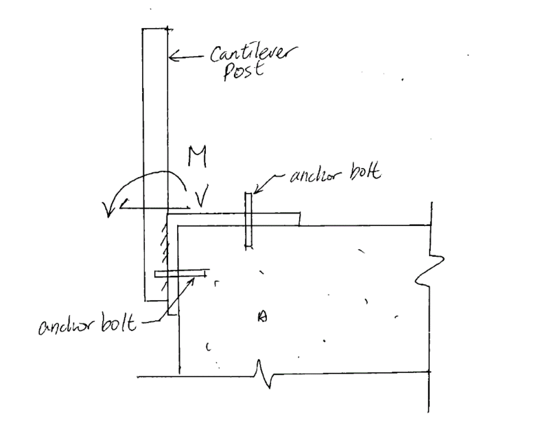
Query_xy4r5p.gif
 
Replies continue below

Recommended for you

You'll probably never know the distribution with much certainty. You can try to distribute the loads in an intelligent manner that reflects stiffness however. For the direction of load shown, I vote for shear in the upper bolt and a compression block against the concrete near the bottom of the post as the moment resisting couple.

I like to debate structural engineering theory -- a lot. If I challenge you on something, know that I'm doing so because I respect your opinion enough to either change it or adopt it.
 
Agreed.
The system would be stable without the bolt into the vertical face of the concrete, so I'd look at shear in the stop bolt and compression block near the bottom.
The distance between this compression block and the bolt in the vertical face would be very small, so I'd expect very little tension.
 
There is a way to calculate to forces on each bolt with reasonably accuracy. Use a traditional graphical mechanical engineering method intended for machine design, the "Instant Center of Rotation" method.

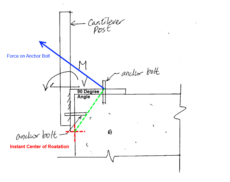
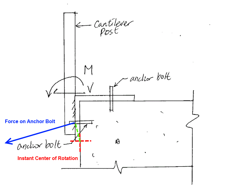
The part (the bracket assembly) is static, but if it could move a tiny amount under load it would rotate about a point. The shear load becomes a second moment about this point. In this case it is easy to determine that point by inspection; it is marked in red on the sketches below, that is the instant center. Draw a radius (shown in green) from the instant center to each anchor bolt nut location. If the bracket assembly was really rotating, the velocity of the two anchor bolt nut points is proportional to the length of thier respective radii. The direction of rotation for each point is shown in blue and is perpendicular to its radius. That is as far as the instant center method goes - to get relative velocities of points on machine parts.

However, assuming the nuts on each anchor bolts are snug under no load, the force applied to the anchor bolts is proportional to the length of the (green) radii. The direction of the force is along the blue lines. Solve for the forces and use trigonometry to obtain the anchor bolt shear and tension loads.

Instant_Center_-1_k9uz3u.gif


Instant_Center_-2_fxqncc.gif


[idea]
[r2d2]
 
I do have a quick question SlideRuleEra.

How did you know the instantaneous center would be at the base of the angle and not at the corner of the slab?

From what I am reading the center is found using your rotation components but I'm curious how you derived the components with a center instead.

Any help would be greatly appreciated!
 

Hysterica (Structural)
14 Jul 15 14:27
Hysterica said:
I do have a quick question SlideRuleEra.

How did you know the instantaneous center would be at the base of the angle and not at the corner of the slab?

The angle iron is "stiffer" at these sizes and forces than the somewhat irregular, non-glued, non-welded concrete corner. Thus, the angle iron will (under realistic loads of a handrail 36 or 42 inches tall under 200 lbf (50 lb per foot) Code loads) "wiggle" and slightly loosen the two anchor bolts, then rotate exactly as drawn about the edge of the angle iron. Walk outside your building at lunch and "wiggle" a few handrails - even those set in tiny 3 inch dia drilled grouted holes.

The other comment about a "pull" force is valid, but the "push" is more dangerous, more likely, larger in force effect on bolt sizes (the push force will size a larger bolt diameter than the pull because the two anchors are not equidistant from the corner), and actually - if solved by a reasonable anchor bolt diameter and depth, will prevent the "pull" effect as well.
 
Oh. Do not place both bolts at the same linear position: Stagger then along the length of the concrete to prevent overlapping the two 45 degree pullout cones.
 
If your shear was in a different direction how might the instantaneous center differ?
L_Bracket_bpohro.png
 
Don't forget prying. That can have a huge impact on your bolt loads.

Maine Professional and Structural Engineer.
 
Hysteria said:
If your shear was in a different direction how might the instantaneous center differ?

A way to solve the problem would have to be revaluated depending on the direction of the force. The instant center method may not be appropriate. It was just a coincidence that the OP's question happened to be inline with what instant centers are intended for (machine design).

[idea]
[r2d2]
 
Status
Not open for further replies.

Part and Inventory Search

Sponsor