Continue to Site

Eng-Tips is the largest engineering community on the Internet

Intelligent Work Forums for Engineering Professionals

  • Congratulations cowski on being selected by the Eng-Tips community for having the most helpful posts in the forums last week. Way to Go!

L vs T shaped foundation 1

Status
Not open for further replies.

bojoka4052

Mechanical
Oct 8, 2021
108
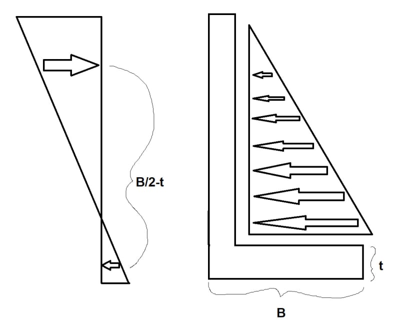
Previous calculations have been done to calculate this inverted T-shaped foundations carrying capacity:
1_vtrgfm.jpg

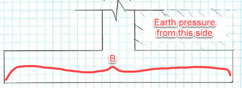
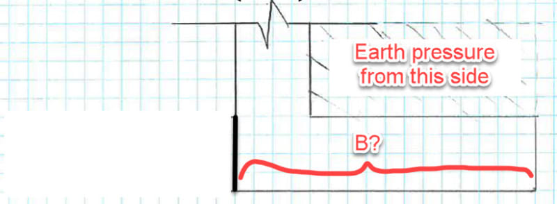
However, my foundation has an L-shape for which I also need to look at both the Serviceability/Ultimate limit state:
2_bkbeo3.jpg


Just roughly speaking, how much do you guys expect the calculations to differ? In theory should it be pretty similar, as everything besides the L foundation not having one of its toes?
 
Replies continue below

Recommended for you

The difference will be substantial. That toe increases the lever arm substantially for overturning resistance.

Even if the B dimension in the L-shape was the same size as the T-shape, the effectiveness of the footing to resist overturning is affected substantially as the resistance is provided much by the backfill. In the T-shape, the lever arm would be approximately 3B/4. For the L-shape, it's (B/2-t) where t is the thickness of the wall. So minimum 25% loss in stability. Potentially it could be more once you take into account the weight of the wall itself now having a lever arm of only t/2 instead of B/2.
 
This appears to be a foundation for a retaining wall, not a traditionally vertically loaded element.

The calculations differ substantially in the two configurations.
 
This footing is similar to a zero lot line foundation, except that usually the foundation is a continuous mat-slab, or has backstrap grade beams for moment and stiffness.
If the loads are light this can work, but keep in mind: 1) the contact stress is triangular at best, 2) deflection now matter more than a symmetrical ftg, and 3) and decent moment now exists at the wall-ftg joint.
 
Lhe reason you don’l reptace an T with a L is subslanliat, quanlilalivety a teasl.
 
In foundations such as this, is overturning moment the culprit, is it basic pressure (defined as "vertical ground pressure" or "earthpressure", not sure what the correct translation is to english), or sliding? Because I see they mention these three things as problems.

How does sliding and "vertical ground pressure" cause problems? Can the foundation slide away, and the earth pressure from the bottom be so much that it causes cracks in the foundation?

 
The wall can slide if there's not enough sliding resistance.

For "vertical ground pressure" you can overload the soil below the footing which would cause the footing to sink or rotate.
 
This is found in any textbook on reinforced concrete design.

The problems are:
1. Sliding. Solving it: make sure that "F_horizontal < N*nu", where "F_horizontal" equals the horizontal loading (from wind, earth pressure and possibly something else), "N" equals the self-weight of the retaining wall and "nu" equals the coefficient of friction between ground and the retaining wall.
2. Overturning. Solution: make sure that "M_stabilizing>M_overturning", with suitable safety factors. Use moment balance around the toe, and apply the necessary loads (atleast self-weight, earth pressure, but possibly also uplift under the footing caused by groundwater) with correct coefficients (i.e., active or passive earth pressure, and so on).
3. Structural strength. Solution: make sure that the footing and cantilevering wall are adequately designed against bending, shear, punching (footing), deflection (wall), cracking (wall).
4. Maximum pressure (stress = M/W + P/A) below footing due to external loads exceeding the bearing capacity of the ground below the footing. Solution: make the footing large enough, or improve the ground conditions, or use piles.

Your colleagues should be able to confirm the required calculations.
 
In my opinion, the most critical aspect of the design of a toeless retaining wall is designing what effectively becomes an opening concrete joint. You'll find copious information about that here: Link
 
Thanks guys, just one more thing. When jayrod12 talks about lever arm, does it mean the one acting on the vertical wall? How can you tell it will be 3B/4 in the T-shape, and(B/2-t) in the L-shape? Is this based on experience? I tried looking for examples, but couldnt find any for these cases. This is how I imagine it in my head:

L-shape:
2_insd7q.jpg

T-shape:
1_ym8wml.jpg


I cant make sense of it because in my drawings L-shapes lever arm looks longer.
 
No, I was talking about the lever arm for the vertical weight of soil for overturning resistance.

The lever arm for the applied overturning is d/3+t if you're calling the footing thickness t. And d is the height from top of retained soil to top of footing.

the b/2-t term I gave previously was assuming the wall thickness (not the footing thickness) was t.

Draw a full free body diagram will all overturning and resisting loads shown at their centroids. Then the terms I wrote above should make more sense.
See attachment. sum the moments about point A in each case.
 
Thanks jayrod, just to summarize:

The only force that gives rotation in the counter-clockwise rotation is Ph (from horizontal soil), here the moment at point A is similar for both T and L footing, since the lever arm doesn't change. But lever arm from point A to Ww, Wf and Pv is significantly longer in the T-foundation compared to L-foundation, which just looking at the drawing we can say that T-footing will resist overturning from horizontal soil force much better?

 
If B is the same in both cases, the L wall will have more overturning resistance because the weight is larger. If you just delete the toe, in which case B is shorter for the L wall, the T wall has more overturning resistance.

The length of the toe is a balancing act between sliding, overturning and bearing resistance. It's also affected by where the stem (wall) need to be in relation to constraints. Often, the wall is on the property boundary to maximise the owners useful land area so you are constrained to the L wall configuration.

A T wall is better for reinforcement detailing but the L can be made to work.
 
Status
Not open for further replies.

Part and Inventory Search

Sponsor