HDStructural
Structural
- Apr 24, 2024
- 123
Hello,
I am designing a garage with an LVL floor beam that supports a 6x6 post going up to the roof. Since it goes up to the roof, there is uplift on this post.
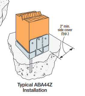
I am looking to anchor this post into the LVL with a concealed connection that won't stick out too much. I am planning to use Simpson Strong Tie's ABU type connection. I am aware this is typically used in concrete.
My question has to do with the design of the 1/2" anchor which would be a lag screw loaded in withdrawal from the top of the LVL. The withdrawal table for lag screws in NDS (Table 12.2A) notes that it is for withdrawal in the side of the member. This connection would be into the top of the member, which is similar to the end for an LVL. Would I just apply the end grain factor for lag screws in withdrawal (0.75) and call it a day?
I'd get my withdrawal values for g=0.50 which is the equivalent specific gravity for microlam LVL's.
Your thoughts are appreciated.

