Continue to Site

Eng-Tips is the largest engineering community on the Internet

Intelligent Work Forums for Engineering Professionals

  • Congratulations cowski on being selected by the Eng-Tips community for having the most helpful posts in the forums last week. Way to Go!

Lag Screws for Steel Plate 2

Status
Not open for further replies.

AKSherpa

Civil/Environmental
Jan 21, 2005
74
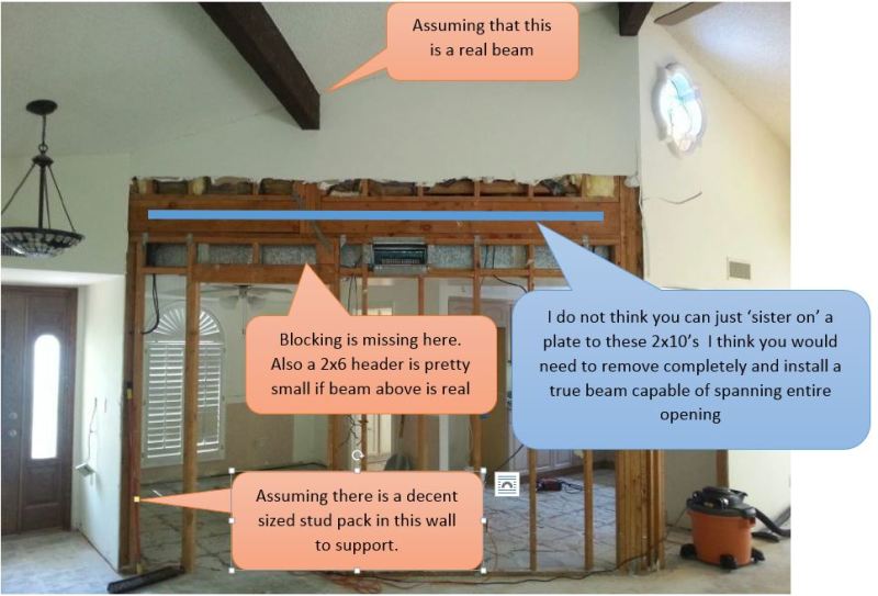
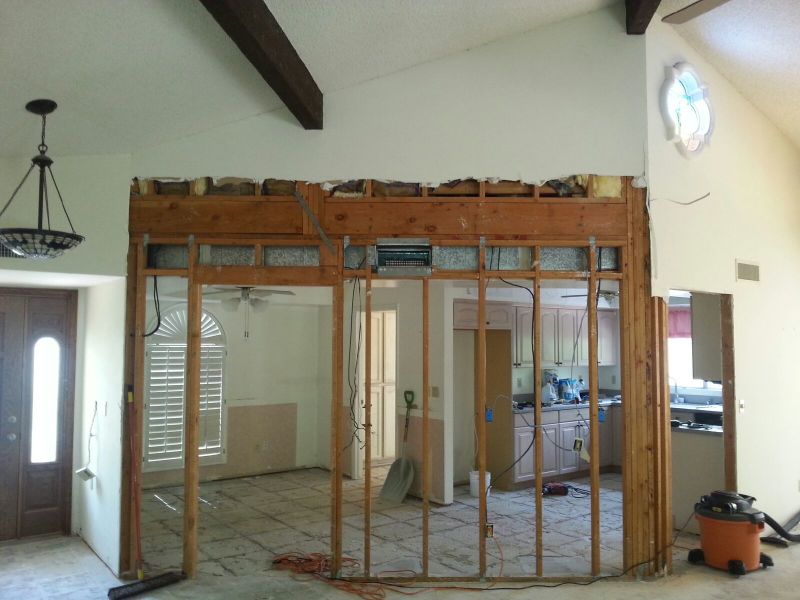
Hello, Please see the attached picture.

I am interested in information related to connecting a 1/4" to 3/8" thick x 12" wide x 13' long steel plate to the 2" x 10" edge board and 2" x 4" top plates shown in this photo for the purpose of removing the load bearing wall. I understand there are other options for reinforcing the wall.

I am particularly interested in information related to what I call "modern" lag screws which I have seen advertised as having higher shear and pullout values than "traditional" lag screws with equivalent diameter.

Thanks

Existing_Wall_jxlkyt.jpg
 
Replies continue below

Recommended for you

Can you support the existing and provide a new steel beam supported on a couple of new pipe columns. These have to be supported on something (more positive beam replacement). You have to determine what the existing 'bearing?' wall is supporting.

Dik
 
That is some interesting framing. Check out the exposed beam being supported by a (4) 2x post bearing on a double 2x plate that is spanning to another post down to header to a single jack stud.

There's a lot going on here...
 
replace the two beams with a glulam
 
Thanks Dik,

There is a flat roof in background under kitchen with membrane roofing material. The living rom is a sloped ceiling with clay tile roof. The 2 x 10 is only a single rim board, 1.5" thick.

I computed factored loads/stresses for a 12' wide opening as follows.

Max Shear = 5,800 lb at left end
Max Bending = 22.5 kip-ft at 58" from left end
Point load from roof beam = 6.3 kips at 54" from left end

I am looking for insight into options for fastening steel plate or channel, 1/4" - 3/8" thick x 12" tall x 13' long to exist. framing. I understand the need to transfer the point load to the steel, as well as transfer the end shear to vertical supports at ends, and fastening steel to wood to prevent LTB.

I am interested in info. concerning "modern" style lag screws including good/bad experiences as well as lag screw pattern info.

Please note, I also know there are simpler/better ways to support the loads such as moving existing vent and installing a traditional wood header.

Thanks
 
yOU may want to have the steel plate act by itself and use the lag screws to provide stability for the plate by securing the plate to the existing wood framing. You have to then provide the new support under the steel plates. A glulam, LVL or PSL, as noted, is a good solution.

Dik
 
Thanks Dik,

That is the idea, the steel is sized to carry the loads by itself with the existing framing only used for lateral stability.

The question is, can the loads be transferred to the steel plate and then back to jack studs(either existing or added)? I am looking for info regarding traditional lag screws say roughly 3/8" diameter. I am also interested in any info regarding the "new" style lag screws that are advertised as having higher strengths with relation to diameter.

JoelTXcive, thanks for the reply. My thoughts exactly. When I first saw the photo it did not appear the framing was constructed to carry the loads I have computed. Studs would be added on left end. I agree a 2 x 6 header is not what I would have used and the blocking directly below is missing, however there is blocking adjacent and it most likely caries the load to the right side of the door frame. The loads I computed include factored wind and live. The home is well sheltered from wind. Most likely the structure has only been stressed at about 1/3 of the loads I am using. It was built in the 70's and did not show any signs of damage. If I was doing the work I think I could prop the sloped roof beam, move the vent, and slip a traditional 4 x 12 header in without any problem.

I am searching for info for future reference concerning fasteners.

Thanks
 
Is this in FL?
Lots of load paths in the existing conf. I believe removal and replacement of the beam is correct way to go.
what about the slab supporting the end studs?
 
I agree with boo1. Getting the load out of the steel back into the wood will be a problem. Just shore it up and replace it.
 
AKSherpa:
I would save the upper top plate, immediately under the 2x10 rim jst., then everything below that gets ripped out; the lower top plate on down and from king stud to king stud, you say approx. 12'. Shore the existing structure as needed, determine the support adequacy of the new end stud packs down at the floor and below, move some wiring hanging down in that wall, and leave the duct work where it is. Then, I’d have a fab. shop fab. an angle iron beam for me, the bot. flg. would probably be about .5 or .626" x 3.0" wide and the web would be about .375" x 12.5" high. You do the calcs., I haven’t. The bot. flg. tucks up under the remaining upper top pl. and the web laps the side of that upper top pl., the rim jst. and the sill pl. above it. The bot. flg. should fit tight (in length) btwn. the king studs and the new studs making up the end bearing columns (stud packs) should be cut so they are all bearing under the stl. beam. The web should be cut about 3" longer than the bot. flg. on each end, so it laps the king studs and can be screwed to them. The web should also be punched for these end lags/screws and for some screws into the rim jst. over the beam length. Shim the wall above out by, at least the stl. web thickness, and hang a cripple header just deep enough to cover the air register. The owner or contractor have a mess on their hands, and we Structural Engineers are not miracle workers, nor can we fix their mess for nothing. That should not be our job, although they always seem to wish that were so.

As for lag screws and the newer structural screws, look in the NDS to see how they are designed and how they work with wood and steel. Also, look at the ICC ESR’s (Evaluation Service Reports) for the individual products. Today, we have so many choices, that it is almost impossible to make a decision. Sure as hell, whatever you design around and spec., the contractor will come back wanting to use something else, from a big box store and China.
 
dhengr

Thanks for the creative ideas, much appreciated. I think I am following you but I have a few questions.

I am assuming you suggest removing one of the wall top plates only to allow room for the steel between the vent and the wood? Otherwise would it be ok to leave the double top plate?

Do you see a way to shore the wall and still allow placement of the angle iron? If not I am thinking it might work to have the angle fabricated with a 1.5" wide bottom flange transitioning to 3" or 3.5" at ends to allow for bearing onto jack studs while also allowing room to shore wall with 2 x material place sideways on the kitchen side of wall.

Am I assuming correctly that the only purpose for the cripple header is to essentially fir down for hanging the wallboard?

Also, what do you think about a flat steel plate screwed to the existing 2 x 10's and wall plates with the plate turning down at the ends and up at the point load from the sloped roof to allow for enough screws to carry the load from the wood to the steel. I understand there are concerns with the footing and soil bearing. I am just talking about the theory of transferring the moment thru the 2 x 10's and 2 x 4 plates via screws and steel and also transferring the shear from the steel to jack studs with screws and no end bearing under the steel.

Thanks very much for your help and insight.
 
AKSherpa:
1.) Yes, the general idea was to remove the lower top pl. to provide space for the stl. beam flg., over the top of the air register opening, without disturbing that opening. I think you made a fuss about that duct in an earlier post. You could probably leave the double top pl. in place and push the duct work down .5" or so. It shouldn’t be too tough to remove the lower top pl.; a little crow bar work, and a sawzal should do it. I do like the horiz. continuity of that double top pl., at that elevation, under that point load and cut up rim jst. That’s gotta be a judgement call as you open things up a bit more, and fine tune the details.

2.) One means of shoring would be the following: A.) On the camera side, open up the sht. rk. about a foot higher, then put a single/double 2x12 on the wall, 13-14' long. At the existing corners put a screw or two through the temp. shoring beam into the existing corner studs to hold it in place, and put 2 or 3 studs under the beam at each end, but also nailed to the existing studs for some improved stability. Now, at the point load, rt. door jamb, and 2+ stud spaces to the right, apply some jacking loads and see if you can lift the rim jst. about .5" over that middle length btwn, jacks, without lifting it off its end supports. Listen for creaking and watch for any cracking, take it easy on the jacking, not all at once. Now, screw the 2x12's off to each wall stud and the stud pack under the clg. beam, and add a couple short studs from the temp. beam up the the clg. beam, fit tight. B.) Just inside the duct work, about 2' into the kitch., from the wall to be removed, build a temp. stud wall, fl. to clg., single sill and top pls., to support roof loads from that side. Cut these studs to fit, they may not all be the same length, you want to hold to roof joist up, not let them settle. C.) The idea is..., you would like to camber this opening and the supported structure up a little before you install and fix the stl. beam in place. Now, you can remove the jacks, you don’t want the rim jst. just to settle back down. Remove the existing wall framing and install the stl. beam, jacking it up to the double top pls., install its end studs and its screw fixings to king studs and the rim jst. With a little planning, you can have the fab’er. drill/punch all the web holes for you. Jack just a little more to unload the shoring, remove the shoring and lower the jacks. As the wall lowers, you want it loading the stl. beam, you don’t want it to have to settle another .5" to start loading the new beam. D.) Before you start the shoring process, put a couple level lines which won’t move around at their end points for reference lines for checking your progress and the cambering and the final stl. beam deflection.

3.) The idea of a 3 or 3.5" wide flg. pl. is to provide some good tension continuity at the bot. of the new beam, and to pick of the point load, from above, in end bearing on the flg. (actually compression perp. to the grain in the double top pls. controls), not with enough screws in shear, into the edges of some split 2x4's. Then, the bot. flg. also provides good solid end bearing on the stud packs at the end reactions. Again, I wouldn’t count on screw are lag bolts to pick up the reactions, that’s a pretty inferior detail for transferring those large structural loads. RE: your single web pl...., I don’t particularly like using the edge of a pl. in bending tension, certainly not if it where sheared or flame cut, maybe UM pl. would be o.k. But, secondly the single pl. doesn’t pick up loads from above nicely and it doesn’t know what to do at the end reactions either. I don’t understand your turning you pl. down and up, at the ends and at the point load respectively. The rim jst. doesn’t carry or transmit any moment, it is discontinuous right at the max. moment. Do some reading in your Timber Framing text books and the NDS to understand how dowel connectors work (that is screws, lag bolts, through bolts, etc.). They are kinda inferior connectors for your application. You can’t get enough of them in the edge face of a 2x without splitting it.

4.) The hanging cripple header is just to frame the top of the opening right under the air register, at what must be a soffit on the kitch. side.

You do have to pay some special attention to my new stl. beam (an angle) an unsymmetrical beam section. It is intended to be slightly heavy, with lower stresses, particularly in compression in the vert. leg. And, also with low deflections. Again, you do the calcs., I haven’t done any.
 
AKS
Obviously no one here thinks it (steel side plate with screws) is a good idea. I agree with that (and the suggestions are good) but you are not asking that question.

Regarding your (repeated) question:
My understanding about lag screws is that "old style" are generally larger diameter and (possibly) inconsistent steel quality. They rely on cross grain bearing behavior mostly.
The thinking about "new style" is that they are generally smaller diameter (often 1/4" or less) and engage the wood materials better by using full length threading. They also tout better consistency of steel strength.

IN THIS CASE - I think the problem will be that the loading is dependent on the stiffness of the existing 2x10 member to be sufficiently stiff as to carry the point loading (from above and to below) out into a sufficient number of screws so that the load is transferred into the steel flitch. I just don't think that is possible (although you don't mention what magnitude of the loads is).
Stiffness will be influenced by the horizontal distance for the concentrated load and the stiffness of the individual screw acting perpendicular to the plate. I don't know if there is standard way to calculate that but I do not think such a system will be effective. In other words, the screws closest to the load will be more stiff (relative to those farther away) and the will attract too much of the load.
I assume that is why everyone is bypassing your question and going straight to the "get something in the underneath the loads" recommendation.


Thanks for the replies.

What is UM plate? I am assuming this is plate with a manufactured edge to reduce the risk of tensile cracking at defects created when torch or shear cut. What type of plates are suggested for flitch plates? Seems like a similar situation as far as the edge in tension?

Instead of screwing a 4 x 12 to the wall to support the roof beam, would it be just as effective to temporarily prop the beam off the concrete slab?

The idea behind turning the steel plate up at the point load and down at the ends would be to provide enough room to allow for lag screw pattern that would transfer the loads between the wood and the steel and vice versa.

I don't think I mentioned the individual loads above so that may be causing some confusion. The factored load from the flat roof in the background of the picture is 300 lb/ft. If the point load of 6.3 kips is transferred directly to a steel plate of sufficient size, the only load being transferred from the 2 x 10's and 2 x 4's to the steel via lag screws is 300 lb/ft. This seems like it could be more manageable?

Thanks again for the great replies
 
"turning the steel plate up..." would be a pretty wacky plate. I don't this there is enough height there to get enough fasteners into the stud pack for 6.3k plus, I wouldn't like the slenderness of such a plate as a column element (up at the post load or down at the bearing ends).

I don't see a practical way to get a flush or nearly flush header condition without installing something physically underneath the post load and on top of the bearing at each end. Screws just won't work that well in single shear when set up like this. You MIGHT be able to get a 1.5" wide MC to go in, in place of the rim. Relatively straightforward shoring of all existing but might be tough to "hang" the far side flat roof rafters (if they are flush with the rim). I'd consider the MC (toes toward the camera) with a plate welded to the bottom for a shelf if needed for flush members on the far side, assuming they can tolerate a notch.

 
dh
I'm curious what a "UM" plate is too.

Also, what is your dislike for steel plate edge in bending tension and not is bending compression?
I'm not disagreeing necessarily, just wondering what you like/dislike about that aspect.
Seems like unbraced and/or slenderness concerns about compression "flange" would be something too. Presumably that can be addressed with enough screws up there though.
 
UM plate is "universal mill plate" and also termed "flat bar". Rolled to width with vertical rollers, and to thickness with horizontal rollers.
 
Houseboy

What capacity would you give a 3/8" lag screw into the SPF stud packs? I am using about 450 lb's.. For 6,300 pounds that would require 14 3/8" lag screws. Seems achievable to me even if you had to turn the plate up or down a little at the ends to make room for them.
 
NDS is at the office but I would guess more like 200 lbs into the edge grain like that and maybe spacing of 3" or more. Probably can offset from one stud to the next so maybe net spacing would be 1.5" (2 screws every 3").
When you write "turn the plate up" do you mean that the plate will have a vertical tab running up at the location of the stud pack? Would that be full pen welded to top edge of the "horizontal" plate?
Still, I don't like the plate as a slender column (even though one my take the position it is braced by the screws).

You'd have a little eccentricity too. Guys that could be addressed with some horizontal tension ties. I'd want that in any case.
 
Status
Not open for further replies.

Part and Inventory Search

Sponsor