Continue to Site

Eng-Tips is the largest engineering community on the Internet

Intelligent Work Forums for Engineering Professionals

  • Congratulations cowski on being selected by the Eng-Tips community for having the most helpful posts in the forums last week. Way to Go!

Lag Screws for Steel Plate 2

Status
Not open for further replies.

AKSherpa

Civil/Environmental
Jan 21, 2005
74
Hello, Please see the attached picture.

I am interested in information related to connecting a 1/4" to 3/8" thick x 12" wide x 13' long steel plate to the 2" x 10" edge board and 2" x 4" top plates shown in this photo for the purpose of removing the load bearing wall. I understand there are other options for reinforcing the wall.

I am particularly interested in information related to what I call "modern" lag screws which I have seen advertised as having higher shear and pullout values than "traditional" lag screws with equivalent diameter.

Thanks
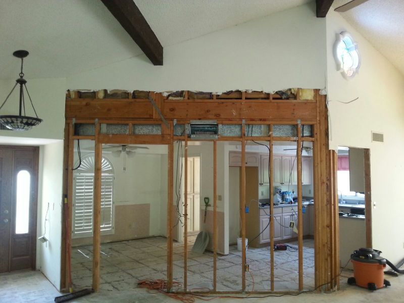
Existing_Wall_jxlkyt.jpg
 
Replies continue below

Recommended for you

HouseBoy:
A UM pl. is a universal mill plate. They are hot rolled to thickness and width, so they have an improved, good clean, edge. Most mat’l. that comes as ‘bar stock’ is hot rolled to size, I believe. I don’t like the rough and/or hardened edge caused by shearing or burning, on the tension edge and the potential of cracking or fracture. These edges need a lot of clean-up, which they usually don’t get. You don’t get the cracking or ripping problem on the compression edge. I was not suggesting that you don’t have to pay attention to the up-standing leg in compression and potential buckling, that’s essentially what my last para. was about, although maybe not too clear. And, as you suggested some proper fixing should solve that problem. I also hate lack of symmetry, but I don’t know how else to get something under the loads to pick them up or distribute them, and then some added mat’l. (the web) to provide some bending stiffness.

While the single pl. is kinda like a flitch pl. on a built-up (reinforced) wooden beam, in this case it is really eccentric w.r.t. the loads and the reaction points, and the OP’er. has some sizeable concentrated loads and reactions which are tough to deal with, with a few screws. This is unlike a flitch pl. btwn. a couple of 2x10's, with a uniform loading atop the beam. The OP’ers loads are all from one side, quite eccentric w.r.t. the pl., and at the moment I can’t imagine getting enough screws in stud grade, 2x edges, at the three primary load points.
 
Thanks all very much for the ideas and thoughts.

Seems to me the concern with eccentricity would be rotating of the plate. With the lateral support of the structure and the minor amount of eccentricity I don't see the plate rotation being an issue.

While we are on the topic, any information concerning lag screw spacing and shear strength values would be of great interest to me. My reference which is a 1991 NDS book indicates the required bolt spacing for full design value is 4D or 1.5" for 3/8" diameter bolts, and row spacing is 1.5D or 9/16" for 3/8" diameter bolts. The table in the lag screw section indicates a 1/4" steel plate side member fastened to S-P-F with 3/8" diameter bolts and loaded perpendicular to the grain has a capacity of 450 pounds. The way I understand the 450 pound capacity needs to be multiplied by Cg, or group factor for multiple fasteners. There is a table of factors for steel connected to wood.

For a 3/8" x 12" steel plate, As = 4.5 in^2. I am not very clear on the As/Am but it seems to me for a 2 x 4, Am = 5.25 in^2. Therefore As/Am = 0.86, much less than the lowest table value of 12??? Seems a little odd but if I refer to the values listed under As/Am = 12, & As = 5, for 10 fasteners in a row Cg = 0.40 resulting in a capacity of 180 pounds per lag screw. Can anyone tell me if I am on the right track as far as the lag screw capacity?

Thanks
 
Status
Not open for further replies.

Part and Inventory Search

Sponsor