Continue to Site

Eng-Tips is the largest engineering community on the Internet

Intelligent Work Forums for Engineering Professionals

  • Congratulations cowski on being selected by the Eng-Tips community for having the most helpful posts in the forums last week. Way to Go!

Large Garages 7

Status
Not open for further replies.

medeek

Structural
Mar 16, 2013
1,104
I'm feeling pretty comfortable with conventionally framed structures as of late and most of my residential work falls with typical parameters that I've dealt with on similar projects.

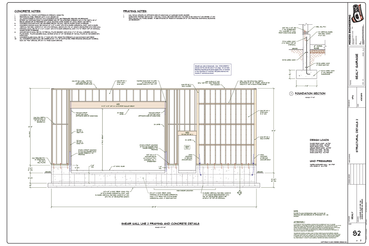
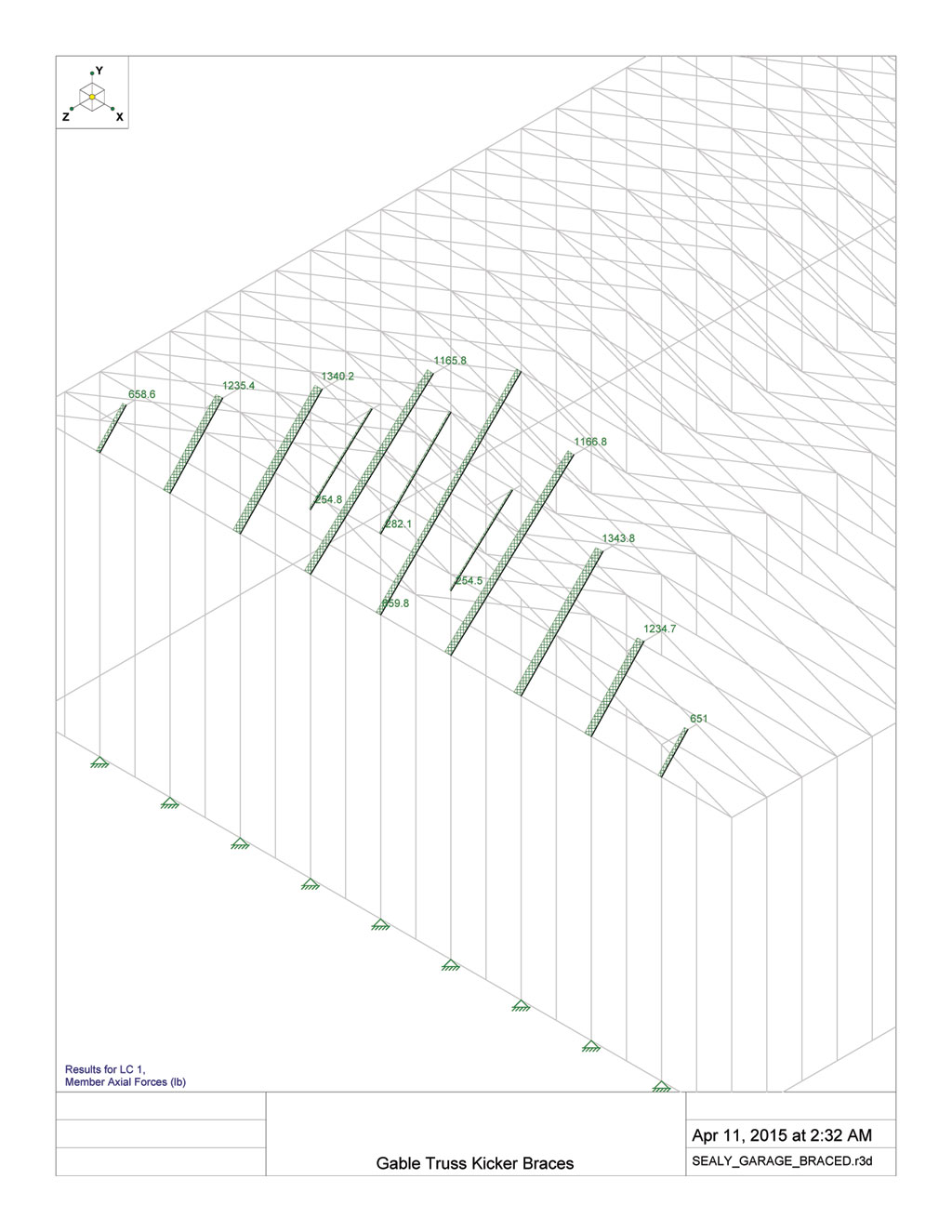
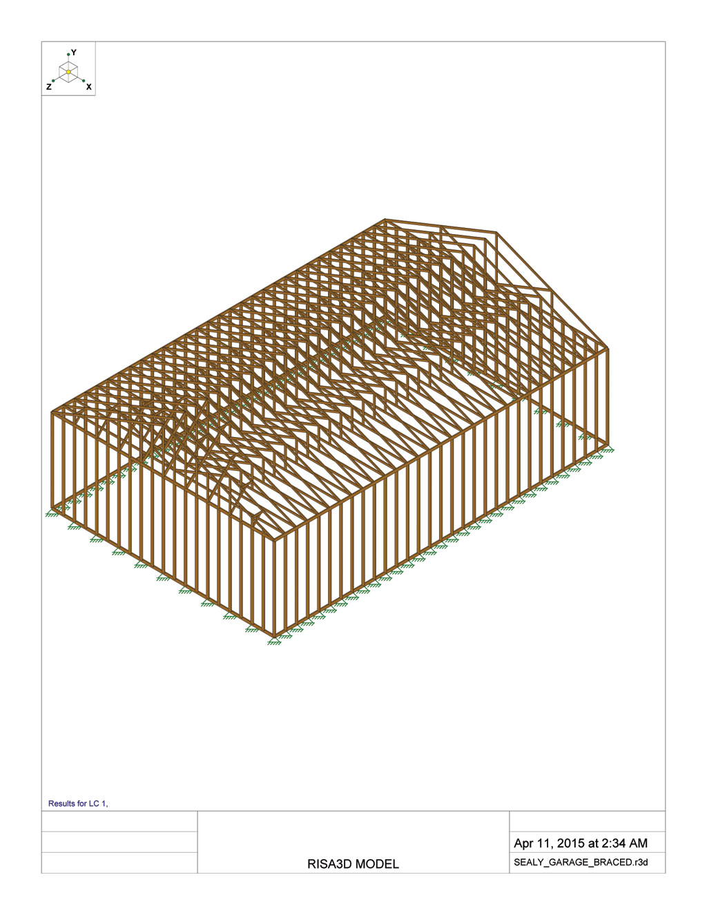
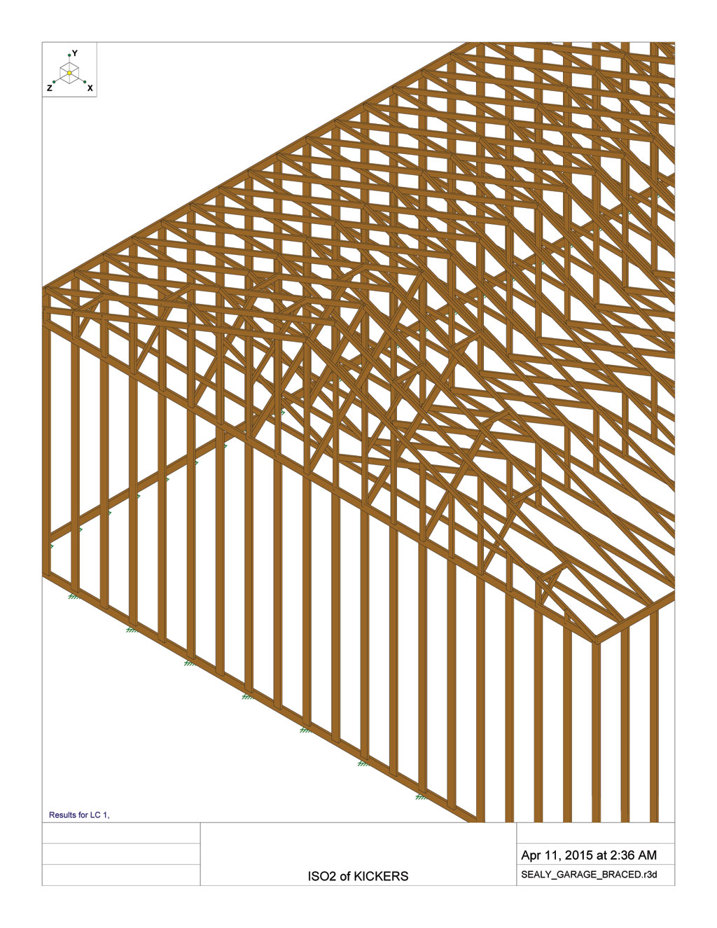
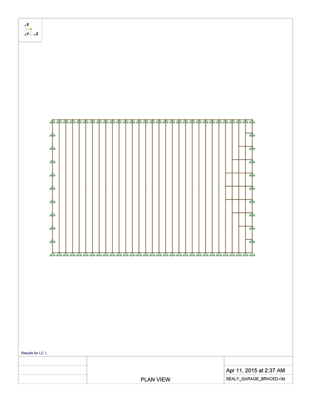
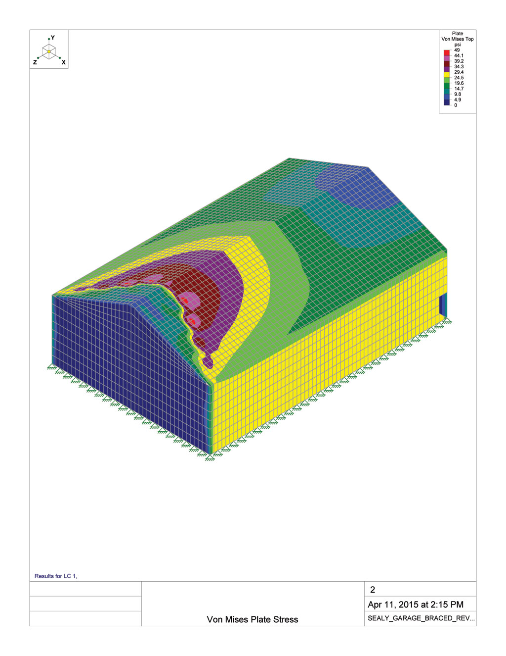
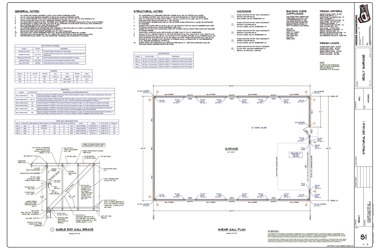
Today a large garage landed on my desk, conventional light wood frame construction. The only thing that really jumps out at me is the size of this structure. 40'x60' rectangle with 40' trusses on 15' high 2x6 walls. I haven't ran all of the numbers yet but I'm sure I can get the stud walls to work with a minor upgrade as well as the shear walls, roof diaphragm and garage door header. The stemwall foundation and slab have been upgraded by the owner and my experience tells me already that bearing loads won't be a problem either.

Nothing really special going on here other than size which causes me to wonder if at some level I may be overlooking something with respect to a structure of this size. As we begin to scale things up are there other codes or factors that come into play that would not otherwise with a smaller structure. There are no internal walls, just the 4 exterior walls with a 18' wide garage door at one of the gable ends and a 3' man door. From a prescriptive standpoint I know this structure breaks all of the IRC braced wall line rules so the IRC is out of the question on this one.

The reason I have a concern here is based on a conversation I had with an architect on a personal project about 10 years ago. At the time I was involved with my brother in a roofing materials distribution business. Being very young and inexperienced I figured I would design our next warehouse. Ultimately we had to have a architect take it over after my initial attempts. His first comment at my conventially light woof framed structure (100'x60'x20' box) was that it was simply too flimsy at that size and we ended up going with CMU for the 20' high walls.

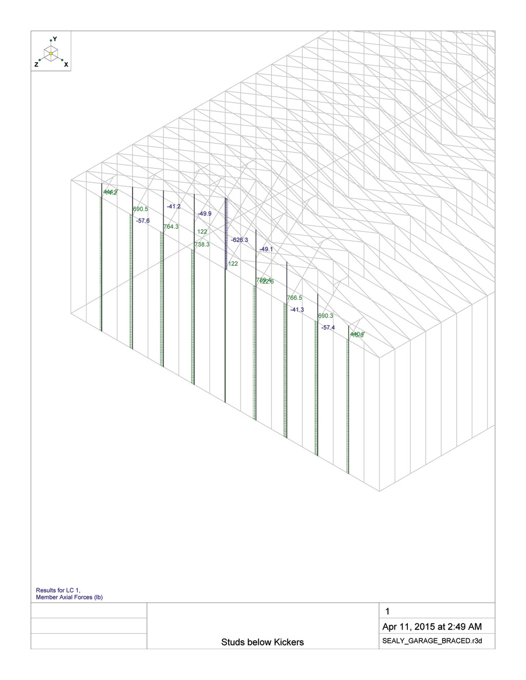
Also in a recent thread on tall walls I am left wondering if an upgraded wall is necessary on the side walls of this structure what would be easier and more "contractor friendly", 2x6 walls spaced at 12" o/c or 2x8 walls at 16" o/c. I typically don't try and specify over DF No. 2 for studs since I think the expense of No. 1 or SS would be unwarranted, easier to bump up to more studs or deeper studs, at least this is my current thinking which may or may not be correct.

A confused student is a good student.
Nathaniel P. Wilkerson, PE
 
Replies continue below

Recommended for you

I guess the board is caching the images or creating smaller versions, here is the update sheet 2:

LARGE_GARAGE_STRUCTURAL2_REV3.jpg


A confused student is a good student.
Nathaniel P. Wilkerson, PE
 
oops, my mistake.
As far as the load sharing - who knows. Make sure the truss designer knows about the new loads.
You are lucky people use concrete foundation walls in your area. In my area, they would have built a 4" brick/4" CMU wall and expect me to do something with it.
 
I wouldn't even know what to do with a CMU foundation, I've never had to deal with one yet.

Available vertical webs are going to be a problem though. The center brace will probably have a center web to brace against (assuming Howe truss and not a Fink) but the next one will not. I can see why people shy away from kickers, its messy. By the time they are finishing installing the diagonal braces (kickers) and the braces for the braces this whole thing is going to look like a rats nest up in the ends of the attic.

A confused student is a good student.
Nathaniel P. Wilkerson, PE
 
The hinge effect is clearly shown here:


The kickers appear to eliminate the hinging but there is still some pinching in of the space between the gable truss and the next truss:


Without any secondary kickers (those above the main kickers tying into the wall top plate) my calculated lateral force to each kicker is 226 plf x 4 ft = 904 lbs, if the diagonal is 45 degrees the compression force in the brace is then 904 lbs x 1.41 = 1278 lbs

The axial loads in the kickers given by RISA3D:

SEALY_GARAGE_KICKERS_AXIAL.jpg


The wall studs loads are:

SEALY_GARAGE_WALL_STUDS.jpg


The RISA Model:

SEALY_GARAGE_MODEL.jpg


Closeup of the gable truss with kickers:

SEALY_GARAGE_KICKERS_CLOSEUP.jpg


Planview:

SEALY_GARAGE_MODEL_PLANVIEW.jpg


A confused student is a good student.
Nathaniel P. Wilkerson, PE
 
You can put a triple truss - say 6 ft back and ladder frame the rest in with 2x4's. That would give you an un-ubstructed kicker path and you can use the ladder framing for attachment of the kickers. Also, do you really need two rows of kicker? Seems it would be cleaner with one.
 
Here's the sketch that I promised above showing why, in the absence of drag struts connecting the diaphragm chords, the effective diaphragm length should be taken to be about half the diaphragm width. The crux of it is my belief that you can't transfer significant tension across plywood joints without initiating perpendicular to grain splitting. Additionally, when we calculate our nail spacings, we're generally only designing for the diaphragm shear and uplift, not the tension forces that would be required to drag applied load through the depth of the diaphragm.

To get any load spread at all within the diaphragm, the plywood sheets require some internal tension capacity. That tension capacity would be unreliable in gypsum sheathing which is why I'm even more skeptical of diaphragm load distribution with ceiling assemblies in the absence of chord to chord drag struts.

20150411%20Diaphragm%20Proposal.JPG


I like to debate structural engineering theory -- a lot. If I challenge you on something, know that I'm doing so because I respect your opinion enough to either change it or adopt it.
 
KootK I'm going to need a few hours to roll your diagram around and give it some thought.

I wish I knew more about FEA and plate modeling. I think if one could establish a realistic model that accounts for various factors such as nail slip and tension etc... it would be interesting to see really how accurate our simplistic assumptions are.

Here is the Von Mises Plate Stress from the model above:

SEALY_GARAGE_PLATES_STRESS1.jpg


I never did take an FEA class in school, wish I had. My other electives (robotics, jet engine design, aerodynamics etc...) are pretty much useless to me now. I guess it is time to find a good text book on FEA and understand plates a little better. I would also like to utilize some FEA models to validate my new FTAO and Portal Frame calculator that I'm working on.

A confused student is a good student.
Nathaniel P. Wilkerson, PE
 
FEM book recommendation: Link. Presents the theory about as simple as it can get and has a great practical chapter on how to model and check.

I like to debate structural engineering theory -- a lot. If I challenge you on something, know that I'm doing so because I respect your opinion enough to either change it or adopt it.
 
@Kootk:

I like your shear model. I imagine a significant amount of tension does occur at the plywood butt joints in reality even if the edge distances are small. I have seen too many instances in practice of plywood acting in pure tension in this manner without failure.
 
KootK -> nice diagram and I appreciate you putting time into this. I think it is correct but I think in reality the plywood and the gypsum board are able to carry quite a bit of tension. The cross grain force caused by the nailing joint is the weak link but when you consider the joints are staggered the cross grain bending is spread to all joist at many nail locations. This is probably why the ceiling performs so well in reality.

EIT
 
While a nice exercise, I feel FEA is pretty worthless for wood structures. Too difficult to accurately model the non-linerarity of the the different synergistic systems. Also, way too many variables in the construction process.
 
medeek: A couple of comments.

1) I attached a gable end wall brace detail. I have others that utilize (2) 2x6 diagonals up to the roof with upside down LU26 hangers connecting the blocking to the trusses. You really only need to figure out the force on the brace and then detail your connections to take the force. Sometimes the Simp. Gable End Wall connectors don't work and you need to use steel angles.

2) The hold-downs at your garage opening will more than likely cause spawling in the concrete. I would recommend using an HDU or something along those lines to avoid the splitting. I have seen many, many straps installed at angles, missing studs when nailing to the studs etc to the point that I don't even look at including them in my drawings any more as well.

3) How are you transferring the out-of-plane force from your garage opening king studs into the roof diaphragm and the stem wall? This can be a critical connection that is generally missed and should be looked at...just like the gable end wall braces.
 
 http://files.engineering.com/getfile.aspx?folder=40fbbf3a-a35b-4549-9eab-c6f7b9d1665c&file=Gable_End_Wall.pdf
CBSE, thank-you for the detail and also your additional comments. I particularly find the comments about the doubled up braces to be interesting, this is along the lines of what I was thinking. I've determined that I've got about 900 lbs of lateral load on some of these braces which is approx. 1275 lbs tension or compression. The GBC connector is just not going to work. As for steel angles connecting the brace to wall top plt. I'm considering two HGA10 on each side of the (2) 2x6 brace, I'm not really finding anything in Simpsons catalog that fits the bill.

My next best option is to simply require braces at 24" o/c, this will get my forces down to more manageable levels.


A confused student is a good student.
Nathaniel P. Wilkerson, PE
 
CBSE, I typically stay away from the strap holdowns for the same reasons you mentioned however in this case the amount of wood utilized for trimmmers and king studs gets me such a distance away from the opening that I though it would be better to use the strap holdowns to help eliminate this eccentricity. I am counting on the STHD14 straps for both uplift and also some lateral (out of plane forces at stemwall). The 5/8" dia. anchor bolts will also pickup some of the lateral at the stemwall at 16" o/c.

A confused student is a good student.
Nathaniel P. Wilkerson, PE
 
Here is my first draft at the Gable End Wall Brace Detail:

GABLE_END_WALL_BRACE.jpg


The overall structural plan for reference:

LARGE_GARAGE_STRUCTURAL1_REV2.jpg


I've decided to try 36" on center spacing since 48" on center has to high of point loads at the connections to the top plate and also at the connection to the roof diaphragm

A confused student is a good student.
Nathaniel P. Wilkerson, PE
 
Now that I've got that more or less worked out back to KootK's diagram.

Take a flat ceiling diaphragm, flip it up vertical, support it at both ends and you have a really tall, thin beam. However the way I see it is that the direction of the rafters or girts play into it. From my recent work on the pole frame structures it can be shown that the diaphragm chord forces are not just at the perimeter as is typically assumed with wood framed diaphragms but rather shared by the internal girts as well.

I would be really interested to read more on the methods used to come up with the diaphragm allowables found in the SDPWS and what their assumptions and simplifications were. Are these numbers from purely empirical testing?

The to further complicate the matter you pitch the roof. Low slope roofs are probably pretty close to the classic diaphragm but what about a 12/12 pitch roof. Does the higher pitch make the diaphragm stronger or weaker? Where does this change in pitch show up in the SDPWS tables? Maybe it is a insignificant factor.

My thinking with the cross grain splitting is what is the failure mode. Will the nails heads pull through the panel first or through the edge before the framing splits. My suspicion is that the nails will pull through the edge of the panel before the framing members splits when the nails are not closely spaced (ie. 6" o/c at edges).

I actually think modeling diaphragm action, nails included would be a good candidate for FEA. I'm just not sure how to model the nails and sheathing effectively. What I am interested in visualizing is how the nails load up in a diaphragm. Do the nail loads mirror the classic diaphragm shear diagram (zero load at the middle) or are there other effects or factors at play that are overlooked by the classical diaphragm model?

A confused student is a good student.
Nathaniel P. Wilkerson, PE
 
Thanks for reviewing my sketch guys. As follow up, I submit the additional sketch shown below. Given Medeek's loads, and the assumption of distributing those loads throughout the entire length of the diaphragm, the first plywood joint would need to transfer about 225 lbs of tension. With a 6" nail spacing, that's equivalent to a 12" strip of plywood with two nails in it holding up a standard olympic barbell loaded with four 45 lb plates. Does our collective intuition still tell us that this would be okay? Ditto for a drywall option?

Note that I'm just having fun with this as an arcane technical discussion. I'm still handling this as everyone else does: full diaphragm engagement, blinders up.

20150413%20Hypothetical%20Sheathing%20Tension.JPG


I like to debate structural engineering theory -- a lot. If I challenge you on something, know that I'm doing so because I respect your opinion enough to either change it or adopt it.
 
I'd stand under that for a short duration (especially if beer was involved as shown)
You have a potential career as an artist :>
 
Status
Not open for further replies.

Part and Inventory Search

Sponsor