Continue to Site

Eng-Tips is the largest engineering community on the Internet

Intelligent Work Forums for Engineering Professionals

  • Congratulations waross on being selected by the Eng-Tips community for having the most helpful posts in the forums last week. Way to Go!

Large Sign Pole Design 2

Status
Not open for further replies.

CBSE

Structural
Feb 5, 2014
309
I have been asked to design a 65ft tall pole for a sign. See attached dimensions. They want a break at 25ft, and then another pole break at the sign which is supposed to have a HSS Tube behind the sign for attachment. Does anyone have any ideas on how to attach these together besides a plate splice with bolts? Is there a way to do some sort of sleeve at the first break from the ground so it looks a little bit cleaner?

I imagine there will be some sort of frequencies that need to be considered with this as well.

Thanks
 
 http://files.engineering.com/getfile.aspx?folder=40cb0ec0-9a33-40bf-8b06-b6d3d1b49ed7&file=Large_Sign_Pole.pdf
Replies continue below

Recommended for you

damorim: I haven't thought about that type of pole. I suppose it wouldn't hurt to ask the client if it is something they would consider. They are quite common now.
 
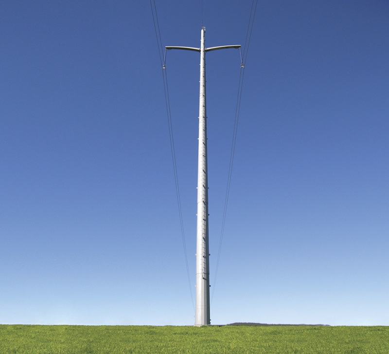
Check out Valmont's website. I think it would be a solution that should definitely be considered. Design would be according to AASHTO's LRFD Specs for Structural Supports for Highway Signs, Luminaires, and Traffic Signals. Monotubular structures like these are quite common and the slip joint provides a nice connection.

utility-structures_pajzs8.jpg
 
FWIW (which ain't much) I don't like the weld either. you could put a sleeve under the top plate (that rests on the lower tube) and bolt on or weld vertically (welds in shear).

the lateral loads coming into the lower tube at a line of welds ... do you like that ? I understand it is a difficult design to link the two tubes. You could use a bolt on sleeve ... fits inside the lower tube, outside the upper, several cross bolts into each tube ...

another day in paradise, or is paradise one day closer ?
 
KootK said:
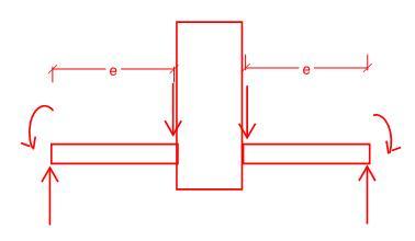
An interesting feature of the detail is that it uses fillet weld pairs in bending to resist gravity loads.

Care to explain this comment Koot? I only see the fillet welds resisting shear, but I am sure there is something I am missing.

Thanks!
 
Koot:
Actually, if I’m reading you comment about the pairs of fillet welds taking the bending action correctly (as you intended it), those welds really aren’t that unusual. Take a unit width (unit circumferential length) of the ring pl. at those welds; with a canti. length of [(D1 - D2)/2, +/-], the radial space btwn. the pipes, +/-; the gravity and lateral loads cause bending on the double fillets, plus shear perpendicular to and in the plane of the ring pl. This doesn’t really load or stress the welds appreciably differently than on a “T” joint with a tension/compression load on the “T” web, plus a bending force on the web. And, we see this detail quite often in everyday service. The important thing about the double fillets, and bending, is that they tend to protect the fillet roots, they prevent prying tension across the roots. Then, the resisting moment is the ring pl. thickness, plus, times the fillet weld cap’y. per inch of circumferential length.
 
I think I see it now. Needed to draw the FBD of the plate. Let me know if this is what you were referencing.
bending_ltdtoe.jpg
 
That's exactly it SNT. Perhaps without the moments at the ends depending on one's perspective.

I like to debate structural engineering theory -- a lot. If I challenge you on something, know that I'm doing so because I respect your opinion enough to either change it or adopt it.
 
We build a lot of these. Most sign people who fabricate these will be familiar with that telescoped/slotted connection. The slot welds will be expected so don't worry about cost. Although that's the first time I've seen that detail with the slot beveled as shown. I'd recommend against that and just use a square sided slot sized with a min slot height of outer pipe thickness + 5/16" (AISC J2.3b). That bevel would add significant shop time.

I'd also recommend against 32" pipe and use either 30" or 36". Much more common and you can get them in almost any thickness from .312" and above(.375/438/500 etc.) 20" and 24" are also very available for the second stage. Most people in this business will have these pipes in stock.

Personally, I like the 'optional' guide ring shown in that detail and usually use something thicker. I have seen an instance where the field welds were done improperly (horribly) and that guide ring would have saved a failure that couldn't be repaired.
 
Good to have an expert in the room. This may be a silly question but will the pieces delivered to site be assembled on the ground or in the air?

I like to debate structural engineering theory -- a lot. If I challenge you on something, know that I'm doing so because I respect your opinion enough to either change it or adopt it.
 
It depends. If the site (and budget) can handle a long load of freight we'll fully assemble them in the shop. But if you start crossing more than one or two state lines that gets prohibitive depending on length.

Looking at this one, I'd expect it to be shipped with the top two stages shop welded together. They'll plant the lower column in the ground then drop in the top piece and field weld it at the 25' level. So field welded in the air. It's difficult to manage pipes like this horizontally. We have rollers in the shop to help...but even then it can be a pain. Gravity is a big assistant. That being said, that one field fillet will be an overhead weld so the welders need to be qualified. That's much easier in the shop with the powered rollers in a horizontal position.

Biggest problem we see (fabricators perspective) is when a pipe is assumed to be perfectly round and it's not, the nice circular rings won't fit. And you can't assume a factory end on pipe is always square. We test fit connections to be field welded.

 
azcats: that's fantastic information. A couple of questions:

1: is it common to use a HSS at the top for the sign to hook to, or do another pipe and sleeve?
2: for foundations, it's pretty big. Like 5' diameter X 16' deep. Is it more common to go shallower or a balance?
 
1. I see more pipe than HSS for that top piece. The cabinet manufacturers usually want that piece as small as possible because it keeps the size (thickness) of their cabinet down and helps with the internal lighting and minimization of shadows. You could check to see if your client (which might be the cabinet manufacturer) has a preference. Looks like 12" nominal (12.75" OD) STD Pipe would be a good size for that cabinet.

2. That's not terribly deep from my perspective. Obviously, I don't know your site conditions. Personally, when possible I usually opt for smaller diameter and a bit more depth. For a 30" pipe I like a 4' diameter pier which would add a couple feet to your depth. Water table or other considerations also come into play there. I also try to avoid reinforcing the annular space and consider the concrete 'soil improvement.'

 
azcats: That's really good info. I have already submitted "Bidding Only" documents and left the HSS at the top. I will look at changing it to a pipe though. You certainly have been helpful in this. Thank you, much appreciated!
 
Status
Not open for further replies.

Part and Inventory Search

Sponsor