Continue to Site

Eng-Tips is the largest engineering community on the Internet

Intelligent Work Forums for Engineering Professionals

  • Congratulations KootK on being selected by the Eng-Tips community for having the most helpful posts in the forums last week. Way to Go!

Larger stress for solid mesh than plate mesh 2

Status
Not open for further replies.

JanEngineer

Mechanical
May 11, 2017
10
I'm making a model for a pressure vessel. First i made one quickly with 3D solid mesh tetra10 noded. But because i wanted to make some adjustments it was easier to make a plate mesh. Locally the stress is larger for my plate mesh than my solid mesh and i don't understand why. Thicknesses are similar and displacement also.
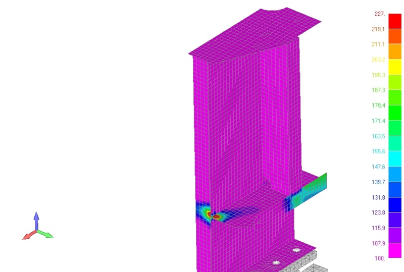
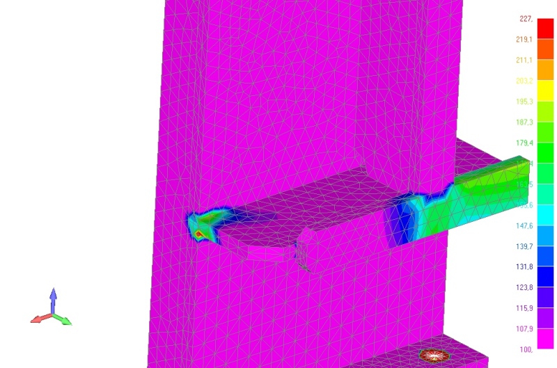
plate_mesh_xjw7xb.jpg
solid_mesh_s7dsoq.jpg


plate_mesh_cfinb5.jpg


Does anyone know how this could be? Is there something wrong with one of my models or is there a fundamental difference between the elements that causes this?
 
Replies continue below

Recommended for you

They both seem to have the same maximum (227). Which feature concerns you?

The two peak stresses on the left of the plate mesh look like a point connection to me. Are you sure the different plates are properly connected all the way along their edges? Check the deformed view to see if any gaps open up.

The highest stress from FEA is usually at an infinite stress concentration so it's meaningless and often different between shells and solids. Perhaps you've already eliminated this by capping the maximum value for the plot? In either case, compare values a small distance away from any internal corners/etc. and don't move closer as you refine the mesh.

Have you checked for convergence with mesh refinement? If not, then you can't really expect two different kinds of elements to match. One could need more refinement than the other.
 
Thanks for your reply. I capped it at 227Mpa so you can see the same scale for both models. Locally the stress is of course larger than this.

What concerns me is that the for the plate mesh i have a larger red spot than for the solid mesh. The solid mesh only has one node that is larger than 227. For the plate mesh there are multiple elements that exceed 227Mpa, even on the plate at the left which has a huge red spot for the plate mesh but not for the solid mesh.

I was under the assumption that globally the stress should be the same for both models. But for me this seems like a significant difference. I could perhaps accept the stress for the solid model because i know i will have some thick welds at the location of the peak stress. But for the plate model I cannot accept the large stresses.

I did check my model for free edges and i do not have any.
 
I see. That large region on the left does look suspicious. I agree that away from trouble areas, the stresses should agree.

Have you checked with mesh refinement? That's quite important since you can't make much of a claim about accuracy without it. It will at least tell you which high stresses don't matter (don't converge) and which do converge to different values.

An idea to check if it's caused by a limitation of shell elements is try redoing both with thinner walls which should reduce the error of shells. See if that brings them closer together.

Other general things to check if you haven't already:[ul]
[li][/li]
[li]The qualitative appearance of the deformed shapes - are the curvatures in the right direction/etc which might reveal boundary condition / connection problems like pinned vs fixed.[/li]
[li]Are the loads the same? Check the net reaction force to confirm that the net applied forces are equal. Especially if the stresses are generally higher overall.[/li]
[li]Make sure you're looking at the shell stress for the correct face. It might depend on how the elements are oriented. Compare with what it shows for the opposite face.[/li]
[/ul]
 
Shell elements will have a linear stress distribution through the thickness so would be no good for calculating the peak stress. Solid elements will capture the stress distribution through the thickness better. In your case the peak stress is at a sharp corner so any results will be meaningless at the corner. In general though tetrahedral elements are poor at calculating stresses at stress concentrations so I'd consider using 20 noded brick elements and then making a comparison with 8 noded shell elements. As has been said though, results should be similar away from the stress concentration in your models.

 
Thanks for all the feedback. The reason why the stress was different is because i applied a pressure. The plate model has a larger surface area, after adjusting for this the stresses are equal for both models (away from stress concentration).
 
Actually the the element orientation got switched around. Still not solved.
 
I hope I'm not getting annoying saying this so many times, but have you done a mesh convergence study? Missing that is by far and away the most common cause of wrong FEA results I see. Run the same models with 3 or 4 mesh densities (can be both coarser and finer than what you have) and make sure the stress approaches the value for the finest mesh. If not, then it hasn't converged and it's definitely wrong.
 
Status
Not open for further replies.

Part and Inventory Search

Sponsor